Specifications
| Type | Three-axis digital accelerometer on an I²C breakout board |
|---|---|
| Chip | Silan SC7A20H, LGA-12, 2 × 2 mm. The back of the board prints SC7A20TR |
| Range | ±2, ±4, ±8 or ±16 g, set in a register. The sketches use ±2 g |
| Resolution | 12-bit output: 1 mg a count at ±2 g, 2, 4 and 8 mg in the wider ranges |
| Zero-g offset | 90 mg typical and 120 mg at most on a mounted chip, about 5° of tilt. Measure it once, level, and subtract it |
| Data rate | 1.56 Hz to 4434 Hz, set in CTRL_REG1. Powered down until that register is written. The sketches use 100 Hz, and 400 Hz to count shakes |
| I²C address | 0x19, fixed. The address pin is a pad under the chip, left open. WHO_AM_I (register 0x0F) reads 0x11 |
| Supply voltage | 3.3 V. The chip runs from 1.71 to 3.6 V and 3.6 V is its absolute maximum; there is no regulator on the board |
| Current | 16 µA at 100 readings a second, 0.5 µA powered down. The power light adds about 1.3 mA |
| Pull-up resistors | 2 × 4.7 kΩ, SDA and SCL to 3V3, always connected |
| Wires to your board | 4 — GND, 3V3, SCL and SDA. A 5 V Arduino Uno needs a TK97 level converter in between |
| Not brought out | INT1 and INT2. The chip's tap, free-fall and orientation detectors still work, read from their registers |
| Board | 22.4 × 30.4 mm, 4-pin right-angle 2.54 mm header with GND on the square pad, two 4.8 mm mounting holes |
| In the box | 1 × TK115 block, right-angle header fitted |
What it does
It feels pushes, in three directions at once, and reports each as a number in g. A board lying still feels one push, the table holding it up against gravity, and that 1 g, shared out between the three axes, is how it knows which way up it is. Anything else it feels is motion: a tilt being made, a shake, a knock, a drop.
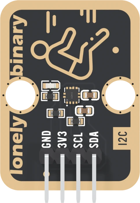
The part doing it is a Silan SC7A20H, 2 mm square, between the two mounting holes. Inside is a small silicon mass on springs, plates beside it that measure how far it has moved, a 12-bit converter and an I²C interface.
The back

There are no jumpers and no pin names on the back. The address is fixed at 0x19, the pull-ups are always on, and the square pad is how you find GND from this side.
Which pin is which
Chip side up, header at the bottom, reading left to right:
| GND | ground | the square pad — count from here |
| 3V3 | 3.3 V only | no regulator: this is the chip's supply |
| SCL | clock | shared, pulled up on the board |
| SDA | data | shared, pulled up on the board |
Wiring, in four lines
- GND to your board's GND. First, every time.
- 3V3 to 3V3. Never 5V: the chip's absolute maximum is 3.6 V.
- SCL to your board's SCL — GPIO 9 on an ESP32-S3, GPIO 22 on an ESP32, GP5 on a Pico.
- SDA to your board's SDA — GPIO 8, GPIO 21, GP4.
For a 5 V Arduino Uno, put a TK97 logic level converter between the two: the Uno's 5V feeds the TK97, and the TK97's 3V3 pin feeds this board.
Example
No library to install. The sketch wakes the chip and prints X, Y and Z about fifty times a second in the form the Serial Plotter draws as three lines. Tip the board and watch the 1 g move between them.
/*
  3-Axis Accelerometer - three lines                    TK115 / /p/tk115

  Wiring. Count from the square pad, which is GND. Chip side up,
  header at the bottom, left to right:

    GND -> GND
    3V3 -> 3V3      (3.3 V only. The chip's limit is 3.6 V, and the
                     board's pull-ups put this pin on SDA and SCL.)
    SCL -> GPIO 9 on an ESP32-S3, GPIO 22 on an ESP32, GP5 on a Pico
    SDA -> GPIO 8 on an ESP32-S3, GPIO 21 on an ESP32, GP4 on a Pico

  Each board's default I2C pins, so nothing in the sketch names them.
  A 5 V Arduino Uno needs a level converter (TK97) in between.

  Arduino IDE
    Tools > Board                 your board, e.g. ESP32S3 Dev Module
    Tools > Port                  the one that appears when you plug in
    Tools > USB CDC On Boot       Enabled   (ESP32-S3 only)
    Library Manager               nothing to install, only Wire
    Serial Plotter                115200
*/

#include <Wire.h>

// 0x19, because the board leaves the chip's SDO pin open and the chip
// pulls it high itself. Tied to GND it would answer at 0x18.
const uint8_t ACCEL_ADDR = 0x19;

bool writeReg(uint8_t reg, uint8_t value) {
  Wire.beginTransmission(ACCEL_ADDR);
  Wire.write(reg);
  Wire.write(value);
  return Wire.endTransmission() == 0;
}

// Read n registers from reg on. Bit 7 set on the register number makes
// the chip step to the next register after every byte.
bool readRegs(uint8_t reg, uint8_t *buf, uint8_t n) {
  Wire.beginTransmission(ACCEL_ADDR);
  Wire.write(reg | 0x80);
  if (Wire.endTransmission(false) != 0) return false;
  if (Wire.requestFrom(ACCEL_ADDR, n) != n) return false;
  for (uint8_t i = 0; i < n; i++) buf[i] = Wire.read();
  return true;
}

// X, Y and Z in g. Low byte first; the 12 bits sit at the top of the
// 16, so shift them down, and at +-2 g every count is then 1 mg.
bool readG(float &x, float &y, float &z) {
  uint8_t b[6];
  if (!readRegs(0x28, b, 6)) return false;       // OUT_X_L .. OUT_Z_H
  x = ((int16_t)(b[1] << 8 | b[0]) >> 4) / 1000.0;
  y = ((int16_t)(b[3] << 8 | b[2]) >> 4) / 1000.0;
  z = ((int16_t)(b[5] << 8 | b[4]) >> 4) / 1000.0;
  return true;
}

void setup() {
  Serial.begin(115200);
  while (!Serial) delay(10);        // native USB: wait for the monitor
  Wire.begin();

  uint8_t id = 0;                    // WHO_AM_I: 0x11 on this chip
  if (!readRegs(0x0F, &id, 1) || id != 0x11) {
    Serial.println("no SC7A20 at 0x19: check GND, then SDA and SCL");
    while (true) delay(100);
  }

  // It powers up asleep. CTRL_REG1: 100 readings a second, X Y Z on.
  writeReg(0x20, 0x57);
  // CTRL_REG4: +-2 g, and never half of one reading and half the next.
  writeReg(0x23, 0x80);
}

void loop() {
  float x, y, z;
  if (!readG(x, y, z)) return;

  // name:value pairs, which the Serial Plotter draws as three lines.
  Serial.print("X:");   Serial.print(x, 3);
  Serial.print(" Y:");  Serial.print(y, 3);
  Serial.print(" Z:");  Serial.println(z, 3);
  delay(20);
}"""
3-Axis Accelerometer - three lines, MicroPython TK115 / /p/tk115
Wiring. Count from the square pad, which is GND. Chip side up,
header at the bottom, left to right:
GND -> GND
3V3 -> 3V3. 3.3 V only: the chip's limit is 3.6 V.
SCL -> GPIO 9 on an ESP32-S3, GPIO 22 on an ESP32, GP5 on a Pico
SDA -> GPIO 8 on an ESP32-S3, GPIO 21 on an ESP32, GP4 on a Pico
Change SDA_PIN and SCL_PIN below for an ESP32 or a Pico.
Thonny
Run > Configure interpreter MicroPython (ESP32) or
MicroPython (Raspberry Pi Pico)
No library needed: the registers are all in this file.
"""
from machine import I2C, Pin
import time
# 0x19: the board leaves the chip's SDO pin open and the chip pulls it
# high itself.
ADDR = 0x19
# GPIO numbers. ESP32-S3: 8 and 9. ESP32: 21 and 22. Pico: 4 and 5.
SDA_PIN = 8
SCL_PIN = 9
i2c = I2C(0, sda=Pin(SDA_PIN), scl=Pin(SCL_PIN), freq=100_000)
try:
found = i2c.readfrom_mem(ADDR, 0x0F, 1)[0] == 0x11 # WHO_AM_I
except OSError:
found = False
if not found:
print("no SC7A20 at 0x19: check GND, then SDA and SCL")
raise SystemExit
# It powers up asleep. CTRL_REG1: 100 readings a second, X Y Z on.
i2c.writeto_mem(ADDR, 0x20, bytes([0x57]))
# CTRL_REG4: +-2 g, and never half of one reading and half the next.
i2c.writeto_mem(ADDR, 0x23, bytes([0x80]))
def axis(lo, hi):
v = (hi << 8) | lo
if v & 0x8000:
v -= 0x10000 # two's complement
return (v >> 4) / 1000 # 12 bits at the top; 1 mg a count
def read_g():
# 0x28 is OUT_X_L; bit 7 set steps through all six registers.
b = i2c.readfrom_mem(ADDR, 0x28 | 0x80, 6)
return axis(b[0], b[1]), axis(b[2], b[3]), axis(b[4], b[5])
# One line of three numbers at a time: Thonny's Plotter draws them.
while True:
x, y, z = read_g()
print("%.3f %.3f %.3f" % (x, y, z))
time.sleep_ms(20)Where to start
The handbook below is eleven short articles with a working figure in each. If you want numbers now, the first reading is the whole build.
If you only read one, read what an accelerometer feels: why a still board reads 1 g, which is the fact everything else here is built on.
And if the numbers look wrong, when it reads wrong sorts the five usual patterns into faults and not-faults.
Wiring diagram
Full board reference: ESP32-S3 pinout.
When it doesn’t work
- Nothing answers at 0x19.
- Check GND first: without it the power light can still glow by borrowing a return path through the signal lines. Then check that SDA and SCL are not swapped, which looks perfectly normal because both lines idle high. Then check 3V3 is on a pin that is actually powered.
- Lying still, Z reads 1.00. Shouldn't it be zero?
- No, 1 g is right. An accelerometer measures the push holding it up, and a board resting on a table is pushed up by exactly 1 g. Only a falling board reads zero. That 1 g, shared between the three axes, is how the board knows which way up it is.
- Which library do I install?
- None. No library in the Arduino Library Manager is written for this chip, and libraries for the similar ST LIS3DH look at address 0x18 and expect WHO_AM_I to be 0x33, so they report no chip. The sketches here read the registers with Wire in about forty lines.
- Every reading is zero.
- The chip is asleep. It powers up with its data rate at zero and takes no readings until CTRL_REG1 (0x20) is written: 0x57 wakes it at 100 readings a second with all three axes on.
- Can I use it with a 5 V Arduino Uno?
- Through a TK97 logic level converter. The chip's pins are rated to 3.6 V at most, and an Uno's Wire library turns on pull-ups to 5 V that lift the idle bus to between about 3.45 and 3.62 V against the board's own. On an ESP32, ESP32-S3 or Pico, wire it directly.
- Can I put two on one bus?
- No: both answer at 0x19 and the address cannot be changed without soldering under the chip. An ESP32 or ESP32-S3 has two I²C buses, so put one on each.
- Can it tell me the heading, or how far it has moved?
- Neither. Turning a level board round leaves the 1 g on the same axis, so there is nothing to measure: heading needs a magnetometer. And distance would have to be worked out from acceleration twice over, which multiplies every small error into a large one within seconds.