analog
10 pages across tutorials, modules, pinouts and guides.
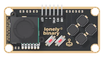
Slim Joystick
A thumb stick and six buttons on one long TinkerBlock board, on six pins. X and Y are two potentiometers, read on analog pins; KEY is the click under the stick, LOW at rest and HIGH when pushed; and all six buttons share BTNS, one analog pin, through a ladder of 10 kΩ resistors that gives each its own voltage. One button reads at a time.
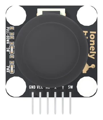
Dual Axis Joystick
A thumbstick on a square TinkerBlock board, on six pins: GND, VCC, NC, X, Y and SW. X and Y are two potentiometers from VCC to GND, read on analog pins; SW is the click under the stick, LOW at rest and HIGH when pressed, with its own pull-down. Every line reaches VCC, so VCC is your board's logic voltage. A PWR light and an SW light show power and each click.
ADS1115 16-Bit ADC I2C Module
Four analog inputs on two wires, with a real 16-bit converter and its own reference — the part you reach for when analogRead is not good enough. Which range to pick, why the supply is the real ceiling, and the two addresses this board can take.
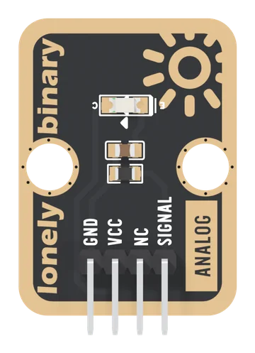
Ambient Light Sensor
A phototransistor and a 4.7 kΩ resistor on a TinkerBlock board: light makes a current, the resistor turns it into a voltage, and SIGNAL rises with the light. A lit room reads low on the scale, bright light flattens just under VCC, and it sees near infrared best.
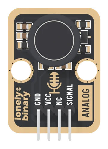
Analog Microphone
An electret capsule and a one-transistor amplifier on a TinkerBlock board. SIGNAL rests at a level set by the transistor's gain and swings above and below it with sound, in a band of roughly 75 Hz to 1 kHz. Read the peak-to-peak over 50 ms: it hears claps, knocks and loud voices, and it is not a recording microphone.
Analog to Digital Signal
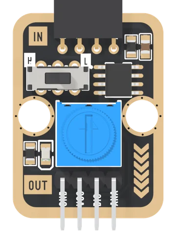
An LM393 comparator on a TinkerBlock board: plug an analog block into the IN socket, set a threshold with the blue knob, and DIG tells your board whether the block's voltage is above or below it. The block's own voltage passes through on ANA, and a slide switch printed H and L turns the answer over.
Disc Potentiometer
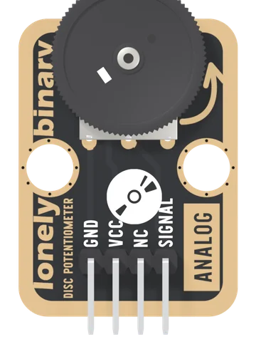
A 10 kΩ thumbwheel potentiometer wired as a voltage divider: turn the wheel and SIGNAL runs from 0 V to VCC, read by one analog pin. The wheel lies flat and overhangs the board's edge, so a thumb turns it from the side.
NTC Thermistor
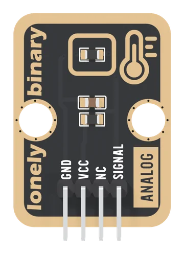
A 10 kΩ NTC thermistor in a divider with a fixed 10 kΩ: SIGNAL is half of VCC at 25 °C and falls as it warms. Read it on any analog pin and turn it into degrees with two lines of arithmetic.
Rotary Potentiometer
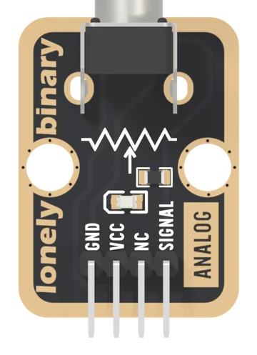
A 10 kΩ linear potentiometer with a knob, wired as a voltage divider: SIGNAL gives 0 V to VCC as you turn. A red LED on the wiper glows as you turn up, and it bends the upper part of the reading: hard on 5 V, less on 3.3 V.
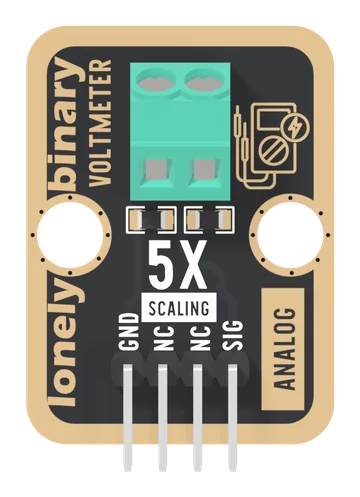
Voltmeter
A 30 kΩ and 7.5 kΩ divider behind a two-screw terminal: SIG is exactly one fifth of the input, so an analog pin can read up to 25 V on a 5 V board and about 15.5 V on a 3.3 V one. DC only, measured from GND.