Specifications
| Type | Analog microphone: an electret capsule and a one-transistor amplifier. SIGNAL swings above and below a resting level; there is no op-amp, comparator or LED |
|---|---|
| Capsule | STW-9767-Z electret capsule, 9.7 mm across, in a foam ring |
| Amplifier | One S8050 NPN transistor, common emitter: 510 kΩ base bias, 1 kΩ collector load, emitter to GND. Gain for small sounds about 40 to 130 times from 5 V, worked out |
| Resting level | Set by the S8050's gain, graded 120 to 400: about 1.6 to 4.0 V from 5 V and 1.2 to 2.7 V from 3.3 V, worked out, not measured. Not half the supply |
| Response | Three 100 nF filters: a band of about 75 Hz to 970 Hz from 5 V (67 to 750 Hz from 3.3 V), strongest near 280 Hz. Worked out from the part values |
| Output | Analog only: the filtered, amplified sound. Read the peak-to-peak over 50 ms. A clap at arm's length swings it by over a volt; talking a metre away by millivolts. Rough sizes |
| Supply | 3.3 V or 5 V on VCC. A loud sound can take SIGNAL up to VCC, so use 3V3 beside an ESP32, ESP32-S3 or Pico and 5V beside an Uno |
| Current | About 1 to 4 mA from 5 V in silence, worked out from the part values; never more than about 5.5 mA |
| Pins to wire | 3 of the 4: GND, VCC and SIGNAL. NC is connected to nothing on the board |
| Header | 4-pin right-angle male, 2.54 mm pitch: GND, VCC, NC, SIGNAL, with GND on the square pad |
| Board | 22.4 × 30.4 mm, two 4.8 mm mounting holes 16 mm apart. No LED on the board |
| In the box | 1 × TK27 block. It also ships inside the TinkerBlock kits |
What it is
A microphone capsule, a transistor, and seven resistors and capacitors. The capsule is an electret microphone: a charged membrane with a tiny transistor of its own inside the can. The board's S8050 transistor amplifies what it hears, about 40 to 130 times from 5V depending on the part, and its output is SIGNAL.
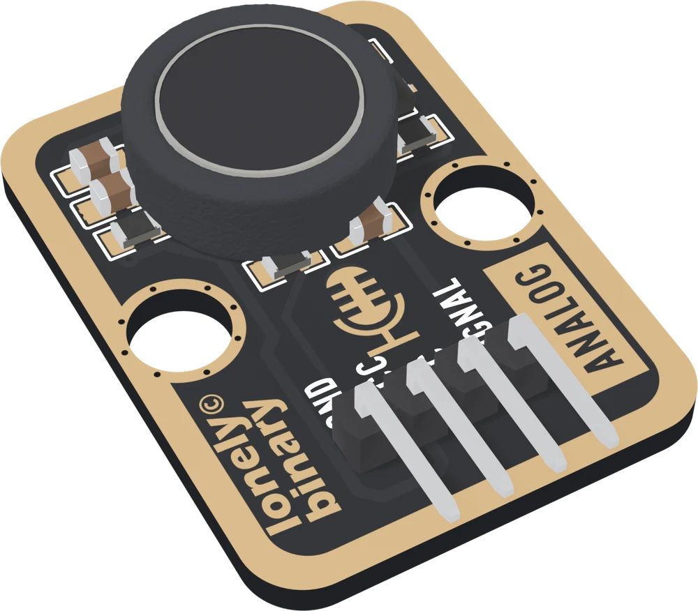
Three things about it decide how a sketch should treat it. SIGNAL rests at a level set by the transistor's gain, anywhere from about 1.6 to 4.0 V from 5V, and sound makes it swing above and below that level, so a single reading means little: read the highest minus the lowest over 50 ms. Three 100 nF capacitors limit it to a band of roughly 75 Hz to 1 kHz, so it hears claps, knocks and loud voices, not quiet speech and not music. And a loud sound can take SIGNAL right up to VCC.
The page this replaces described an op-amp, an output centred at half the supply, and a level that rises with loudness. The board has no op-amp, its resting level is not half the supply, and a single reading does not rise with loudness.
Resting level and swing
| Your board | VCC to | Resting level | Talking, 1 m | Clap, arm's length |
|---|---|---|---|---|
| Arduino Uno | 5V | about 325 to 815 of 1023 | a few counts | a few hundred counts |
| ESP32, ESP32-S3 | 3V3 | about 1.2 to 2.7 V | inside the ADC's own noise | over a volt |
| Raspberry Pi Pico | 3V3 | about 380 to 830 of 1023 | a few counts | a few hundred counts |
The resting levels are worked out for the S8050's datasheet range, not measured. The swings are rough sizes from a comparable capsule's sensitivity, because this capsule's own is not published. Your numbers will differ; the gap between talking and a clap will not.
Which pin is which
Parts up, header at the bottom, reading left to right:
| GND | to your board's GND | the square pad: count from here |
| VCC | to 3V3 or 5V | your board's logic voltage |
| NC | nothing | not connected on the board |
| SIGNAL | to an analog input | swings around its resting level |
The back prints TK27 ANALOG MIC SENSOR instead of pin names. Turned over, the square pad is on the right, and it is still GND. There is no LED: test it by clapping and watching the swing.
Wiring, in three lines
- GND to your board's GND.
- VCC to 5V on an Uno, 3V3 on an ESP32, ESP32-S3 or Pico.
- SIGNAL to an analog pin: A0 on an Uno, GPIO 34 on an ESP32, GPIO 4 on an ESP32-S3, GP26 on a Pico. On an ESP32, use an ADC1 pin so Wi-Fi does not stop the reading.
Leave NC unconnected.
Example
// The analog pin SIGNAL is wired to.
// Uno: A0. ESP32: 34. ESP32-S3: 4. Pico: 26.
const int MIC_PIN = A0;

void setup() {
  Serial.begin(115200);
}

void loop() {
  // Highest minus lowest over 50 ms: the swing, which grows with
  // loudness. The resting level cancels out of it.
  int lo = 32767;
  int hi = -1;
  unsigned long start = millis();
  while (millis() - start < 50) {
    int r = analogRead(MIC_PIN);
    if (r < lo) lo = r;
    if (r > hi) hi = r;
  }
  Serial.println(hi - lo);
}import sys
import time
from machine import ADC, Pin
# The GPIO number SIGNAL is wired to. ESP32: 34. ESP32-S3: 4. Pico: 26.
adc = ADC(Pin(4))
if sys.platform == "esp32":
adc.atten(ADC.ATTN_11DB) # the full range, to about 3.1 V
while True:
lo = 65535
hi = 0
start = time.ticks_ms()
while time.ticks_diff(time.ticks_ms(), start) < 50:
r = adc.read_u16()
lo = min(lo, r)
hi = max(hi, r)
print(hi - lo) # the swing: louder, biggerWhere to start
The handbook below is ten short articles, each with a working figure. The first reading is the whole build in three wires and a few lines, and resting level and swing turns it into one number that means something.
For something that reacts to a clap, a clap switch is the project. If the resting level puzzles you, the resting level works it out; if talking does nothing, three filters says why.
When it doesn’t work
- It reads about the same number all the time and barely moves. Is it broken?
- Probably not. In silence SIGNAL sits at a resting level, and a single reading of a quiet room is that level. Clap a hand's length from the capsule while printing the peak-to-peak over 50 ms: if it jumps by hundreds of millivolts, the block works. Ordinary talking a metre away moves it by only a few millivolts.
- Why is the resting level not half the supply?
- Because nothing sets it to half. It is VCC minus the transistor's current through 1 kΩ, and that current is the transistor's gain times a base current fixed by 510 kΩ. The S8050's gain is graded from 120 to 400, so from 5 V one board rests near 1.6 V and another near 4 V. Measure it at start-up; the swing does not depend on it.
- Does a louder sound give a higher reading?
- Not a single reading. Sound makes SIGNAL swing both ways around the resting level, so one reading can land anywhere on the wave. The number that grows with loudness is the highest reading minus the lowest over a window, about 50 ms. It stops growing once a very loud sound clips at VCC and near 0 V.
- Should VCC go to 3V3 or 5V?
- To your board's logic voltage: 3V3 on an ESP32, ESP32-S3 or Pico, 5V on an Uno. A loud sound turns the transistor off for an instant and SIGNAL goes up to VCC, so 5V on VCC can put 5 V on a 3.3 V pin.
- Can I record speech or music with it?
- Not usefully. Its filters pass roughly 75 Hz to 1 kHz, ordinary speech is a swing of a few millivolts, and recording needs thousands of evenly timed samples a second. For recording, use a digital I2S microphone on a board with I2S.
- Where is the sensitivity knob?
- There is none, and no on-off output. SIGNAL is analog only, and your sketch sets the threshold: measure the quiet swing at start-up and fire a fixed margin above it, as the clap switch in the handbook does.