Specifications
| Type | Thumb stick with a centre click, and six push buttons, on one board: eight inputs on four signal pins |
|---|---|
| Stick | Two potentiometers from 3V3 to GND, one per axis, on X and Y. Rests near half of 3V3; tilts about 16° each way |
| Click | KEY: a switch to 3V3 under the stick with a 10 kΩ pull-down. LOW at rest, HIGH while pushed down. Read it as INPUT |
| Buttons | 6 on one analog pin, BTNS: two 3 × 6 mm with red caps and four 6 × 6 mm in a diamond |
| Button levels | A ladder of 10 kΩ resistors: all of 3V3, 1/2, 1/3, 1/4, 1/5 or 1/6, by button; 0 V with none pressed. One button reads at a time |
| Supply | 3V3, as printed on the header. This handbook wires it to 3V3 on every board, the Uno included |
| Current | At most 0.33 mA through the ladder, with U11 held, and 0.33 mA through the pull-down while clicked; the stick's tracks as well, whose resistance is not published |
| Pins to wire | All 6: 3V3, GND, three analog inputs for X, Y and BTNS, and one digital pin for KEY. No NC pin |
| Header | 6-pin right-angle male, 2.54 mm pitch, along the top edge: KEY, Y, X, BTNS, 3V3, GND, with GND on the square pad |
| Board | 62.4 × 30.4 mm, four 4.8 mm mounting holes, one in each corner. No LED on the board |
What it is
A thumb stick and six buttons on the long TinkerBlock board. The stick tilts along two axes and clicks when pushed straight down, so with the buttons that is eight inputs, and they come out on six pins: X, Y, BTNS, KEY, 3V3 and GND.
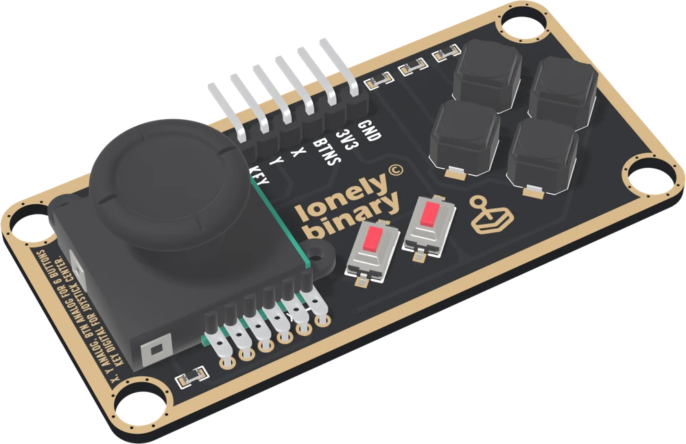
X and Y are two potentiometers under the stick's cap, each a carbon track from 3V3 to GND with a wiper the stick drags along it. Let go, each rests near half of 3V3; tilted, it moves towards one end.
KEY is a switch under the stick, to 3V3, with a 10 kΩ pull-down on the board. It reads LOW at rest and HIGH while clicked.
BTNS is all six buttons on one analog pin. A ladder of 10 kΩ resistors
gives each button its own share of 3V3, so one analogRead says which is
pressed. The cost is that it reads one at a time: press two, and the one
nearer BTNS in the ladder is the only one that shows.
The six buttons
Each switch has its designator printed beside it. With the parts up and the header at the top:
| Button | Where | BTNS | at 3.3 V | The sketches' line |
|---|---|---|---|---|
| U11 | red, left | all of 3V3 | 3.30 V | above 2475 mV |
| U10 | red, right | 1/2 | 1.65 V | above 1375 mV |
| U5 | diamond, bottom | 1/3 | 1.10 V | above 963 mV |
| U7 | diamond, left | 1/4 | 0.83 V | above 743 mV |
| U8 | diamond, top | 1/5 | 0.66 V | above 605 mV |
| U6 | diamond, right | 1/6 | 0.55 V | above 275 mV |
| none | 0 | 0 V | below 275 mV |
Pressed together, the one higher in this table wins, and the other does not show at all.
Which pin is which
Parts up, header along the top, reading left to right:
| KEY | to a digital pin | the click. LOW at rest, HIGH pushed. INPUT, not INPUT_PULLUP |
| Y | to an analog pin | one axis of the stick |
| X | to an analog pin | the other axis |
| BTNS | to an analog pin | all six buttons |
| 3V3 | to 3V3 | on every board, the Uno included |
| GND | to your board's GND | the square pad: count from here |
The back prints TK21 SLIM JOYSTICK and no pin names. Turned over, the square pad is on the left, and it is still GND. There is no LED: test it by reading it.
Wiring
| Board | X | Y | BTNS | KEY | 3V3 to |
|---|---|---|---|---|---|
| Arduino Uno | A0 | A1 | A2 | D2 | 3.3V |
| ESP32 | GPIO 34 | GPIO 35 | GPIO 32 | GPIO 25 | 3V3 |
| ESP32-S3 | GPIO 4 | GPIO 5 | GPIO 6 | GPIO 7 | 3V3 |
| Raspberry Pi Pico | GP26 | GP27 | GP28 | GP15 | 3V3(OUT) |
On the ESP32s, X, Y and BTNS are on ADC1, which keeps working with Wi-Fi on. On an Uno, everything tops out at 3.3 V of the ADC's 5 V: about 675 of 1023.
Example
// Uno: A0 A1 A2 2. ESP32: 34 35 32 25. ESP32-S3: 4 5 6 7. Pico: 26 27 28 15.
const int X_PIN = 4, Y_PIN = 5, BTNS_PIN = 6, KEY_PIN = 7;
const float FULL_SCALE_MV = 5000.0;   // Uno and Pico only. Pico: 3300.

const char* BUTTON_NAME[] = {"U11", "U10", "U5", "U7", "U8", "U6"};
const int LIMIT_MV[] = {2475, 1375, 963, 743, 605, 275};

float readMv(int pin) {
#if defined(ARDUINO_ARCH_ESP32)
  return analogReadMilliVolts(pin);
#else
  return analogRead(pin) * FULL_SCALE_MV / 1023.0;
#endif
}

void setup() {
  Serial.begin(115200);
  pinMode(KEY_PIN, INPUT);            // R1 on the board pulls it down
}

void loop() {
  float mv = readMv(BTNS_PIN);
  int b = -1;
  for (int i = 0; i < 6 && b < 0; i++) {
    if (mv > LIMIT_MV[i]) b = i;
  }
  Serial.print("X ");
  Serial.print(analogRead(X_PIN));
  Serial.print("  Y ");
  Serial.print(analogRead(Y_PIN));
  Serial.print("  KEY ");
  Serial.print(digitalRead(KEY_PIN)); // 1 while clicked
  Serial.print("  ");
  Serial.println(b < 0 ? "none" : BUTTON_NAME[b]);
  delay(200);
}import sys
import time
from machine import ADC, Pin
# ESP32: 34 35 32 25. ESP32-S3: 4 5 6 7. Pico: 26 27 28 15.
X_PIN, Y_PIN, BTNS_PIN, KEY_PIN = 4, 5, 6, 7
BUTTON_NAME = ("U11", "U10", "U5", "U7", "U8", "U6")
LIMIT_MV = (2475, 1375, 963, 743, 605, 275)
ESP = sys.platform == "esp32"
def analog(pin):
adc = ADC(Pin(pin))
if ESP:
adc.atten(ADC.ATTN_11DB) # the full range, to about 3.1 V
return adc
x_adc, y_adc, btns = analog(X_PIN), analog(Y_PIN), analog(BTNS_PIN)
key = Pin(KEY_PIN, Pin.IN) # R1 on the board pulls it down
while True:
mv = btns.read_uv() / 1000 if ESP else btns.read_u16() * 3300 / 65535
b = next((n for n, lim in zip(BUTTON_NAME, LIMIT_MV) if mv > lim), "none")
print("X", x_adc.read_u16(), "Y", y_adc.read_u16(), "KEY", key.value(), b)
time.sleep_ms(200)Where to start
The handbook below is eleven short articles, each with a working figure. The first read is the whole build in six wires, and a ladder of resistors is how six buttons fit on one pin.
For a stick that reads 0 when let go, a centre and a dead zone is the sketch. For everything on the board at once, steering a dot. And before building anything that needs two buttons pressed together, read one button at a time.
When it doesn’t work
- Why does BTNS need an analog pin?
- Because all six buttons share it, and each one lifts it to a different voltage: all of 3V3, a half, a third, a quarter, a fifth or a sixth. Nothing pressed is 0 V. A digital pin sees only HIGH or LOW, so it can tell at most one or two of them apart. analogRead tells all six.
- Can I press two buttons at once?
- You can press them, but only one reads. The button nearer BTNS in the ladder wins outright, in the order U11, U10, U5, U7, U8, U6, and the reading is exactly the same as that button alone. For two inputs at once, use the stick's click, KEY, which is its own pin, or the stick itself.
- KEY reads LOW when I am not pressing it. Is that right?
- Yes. A 10 kΩ resistor on the board pulls KEY down to 0 V, and pushing the stick straight down joins it to 3V3. So it is LOW at rest and HIGH while clicked, the opposite of most buttons. Set the pin to INPUT; INPUT_PULLUP would fight the resistor on the board.
- Should 3V3 go to 3V3 on an Arduino Uno?
- This handbook says yes: the header is printed 3V3, and the Uno has a 3.3V pin. Every reading is then a share of 3.3 V, so on the Uno's 5 V scale the stick and buttons top out near 675 of 1023. The button lines in the handbook's sketches are drawn for 3.3 V; with 5V on the header, most buttons read as the wrong one.
- Why does the stick not read exactly the middle when I let go?
- No thumb stick does. Each axis springs back near the middle of its track, not onto it, and X and Y rest in slightly different places. Measure the centre when the sketch starts, with the stick let go, and treat anything within a few per cent of it as 0.
- Which way does each axis go up?
- It depends on how the stick sits and how you hold the board, and the joystick's drawing does not say. The first sketch in the handbook prints both axes so you can push the stick each way and see; the steering sketch has a line to flip each one.