Only one way round
Every base prints a warning on its back about inserting the board the wrong way. Here is what the wrong way actually connects: the ESP32's 5 volt pin to its own ground, and the base's 3.3 volt rail to a flash pin.
The warning, and what is behind it
The back of every base carries this, in white capitals:
The ESP32 board fits into the base in only one direction. Align it with the USB mark before plugging in. Inserting it the wrong way can permanently damage your board.
That is true, and it is worth knowing why, because "can damage" reads like a disclaimer and this one is arithmetic.
What meets what
The sockets are nineteen ways each and the board is nineteen pins a side, so the board physically fits both ways round. Turn it end for end and every pin still lands in a socket — just not the socket it was meant for.
Two pins decide it. The board's 5V pin is at the USB end of the left-hand row. The base's socket at that position is wired to ground. At the opposite corner the board's ground pin arrives in the socket wired to 5 V. Between them, the base connects the USB supply to its own return, through the dev board.
What limits the current after that is your USB port. A laptop shuts the port down and usually recovers. A charger delivers what it is asked for, through a Schottky diode and a length of copper trace that were never meant to carry it.
Meanwhile, at the antenna end, the base's 3.3 volt rail has landed on GPIO 6 — one of the six pins wired to the flash chip inside the module's metal can. Anything on the base's 3V3 edge row is now connected to it.
The one thing to look at
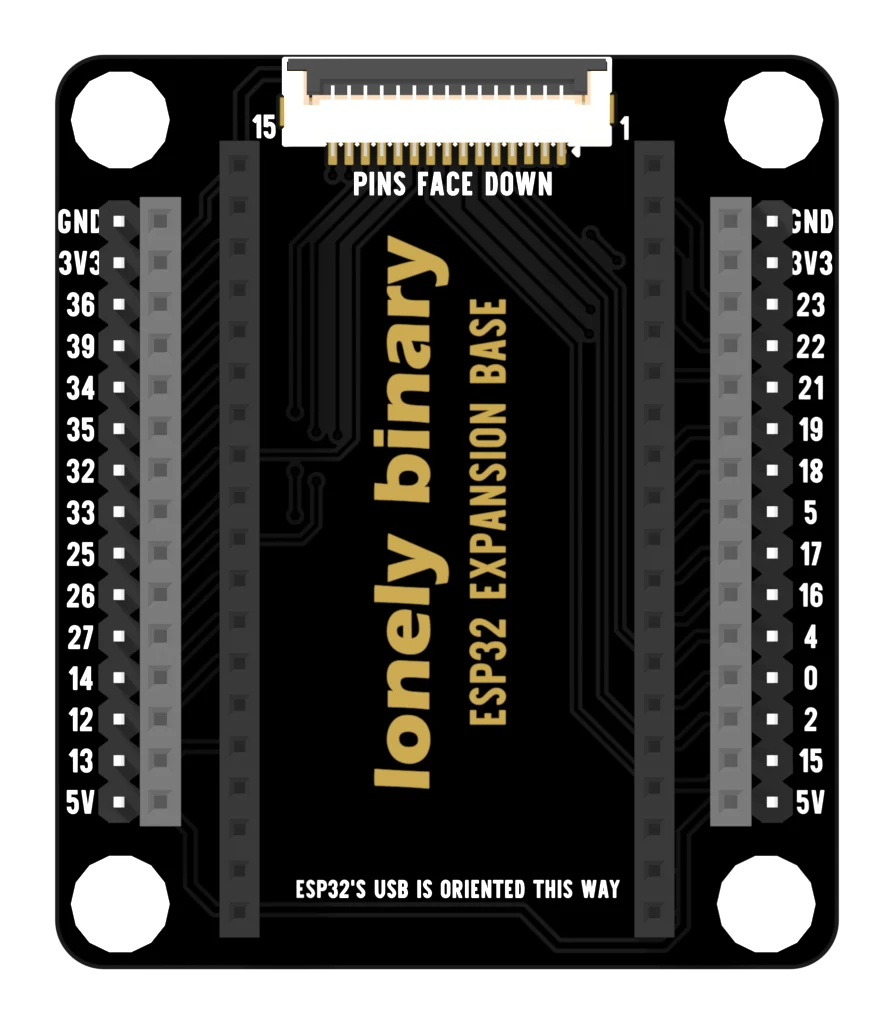
Seat the board with its USB-C socket over that line. The 3V3 row is then at the antenna end and the 5V row is at the USB end, which is the second check if the base is already buried in a project and the text is hidden.
Press straight down, a thumb at each end. Plug the cable in afterwards, not before.
When it does not work
Look at the top face of the base for the line ESP32'S USB IS ORIENTED THIS WAY. The USB-C socket on the dev board goes at that end. If the base is already wired into something and you cannot read it, the other tell is the edge labels: the row marked 3V3 is at the antenna end and the row marked 5V is at the USB end.
Unplug everything. A laptop's USB port current-limits and usually comes back after a reboot; a powered hub may need unplugging from the wall. Then check the dev board on its own, on a different port, before you put it near the base again.
Stiff is normal the first few times — thirty-eight gold pins into thirty-eight new sockets is a lot of friction. Press straight down with a thumb at each end rather than rocking it in from one corner, which bends pins. If it will not go at all, count the pins: a 30-pin or 36-pin board is not this board.
Do not. Seat the board on the base first, look at it, and plug the cable in last. Nothing is damaged by pins arriving in the wrong order when there is no power behind them.
The 2.54 mm board: every pin out twice, on pins and sockets.
The expansion base →Edit this page — content/books/esp32-base/only-one-way-round.mdx
Questions about this product
See what other owners have asked, and read their solutions.
This page covers several products. Choose yours to see the right discussions.
Discuss this article
Ask about this page. The answer stays here, on the page it belongs to, for whoever hits the same wall next.