Specifications
| In the range | Four bases for one board: expansion (2.54 mm pins and sockets), PinPulse (the same, with 24 LEDs), pluggable terminal (push-in) and screw terminal |
|---|---|
| Fits | The 38-pin Lonely Binary ESP32 — 19 pins a side, 25.4 mm between the rows. A 30-pin or 36-pin board from elsewhere does not seat |
| GPIOs at the edge | 24 on the expansion and PinPulse bases, 20 on the pluggable terminal base, 19 on the screw terminal base |
| Edge rows | Expansion and PinPulse: 2 rows of 15 on each side at 2.54 mm, one of pins and one of sockets, so either end of a jumper fits |
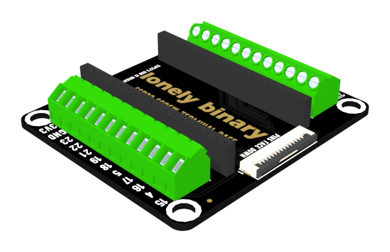
| Terminals | Pluggable and screw bases: 2 blocks of 12 on each board at 3.5 mm, push-in on one and screw on the other |
| Display connector | 15-way FPC at 1.0 mm pitch, on all four bases: 13 GPIOs plus 3V3 and GND, contacts facing down, pin table printed on the back |
| Power at the edge | 3V3 and GND on both sides of every base. 5V on the expansion, PinPulse and screw bases; the pluggable terminal base has none |
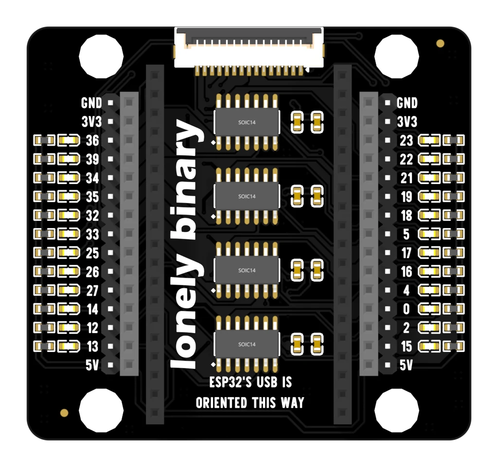
| LEDs | PinPulse only: 24, one per GPIO, driven from the 5 V rail by 4 × SN74HC04 inverters through 5.1 kΩ, so a lit pin is loaded by a CMOS input and nothing else |
| Never brought out | GPIO 1 and 3, the USB serial link, and GPIO 6 to 11, the module's flash bus — on all four bases |
| Mounting | 4 corner holes on every base, sized to take major brand construction bricks |
| Size | 48 × 56 mm for the expansion base, 60 × 56 mm for PinPulse, 64 × 56 mm for the two terminal bases, measured across the connectors |
What a base is
An ESP32 arrives with thirty-eight pins soldered on and nowhere to put them. A base is the board it drops into: two nineteen-way sockets in the middle, every usable pin brought back out at the edges, four mounting holes, and a fifteen-way ribbon socket for a display.
Four of them share this page, because the question anybody holding one asks is the same — which way round, and where did my pin go — and the second half of that is a comparison.
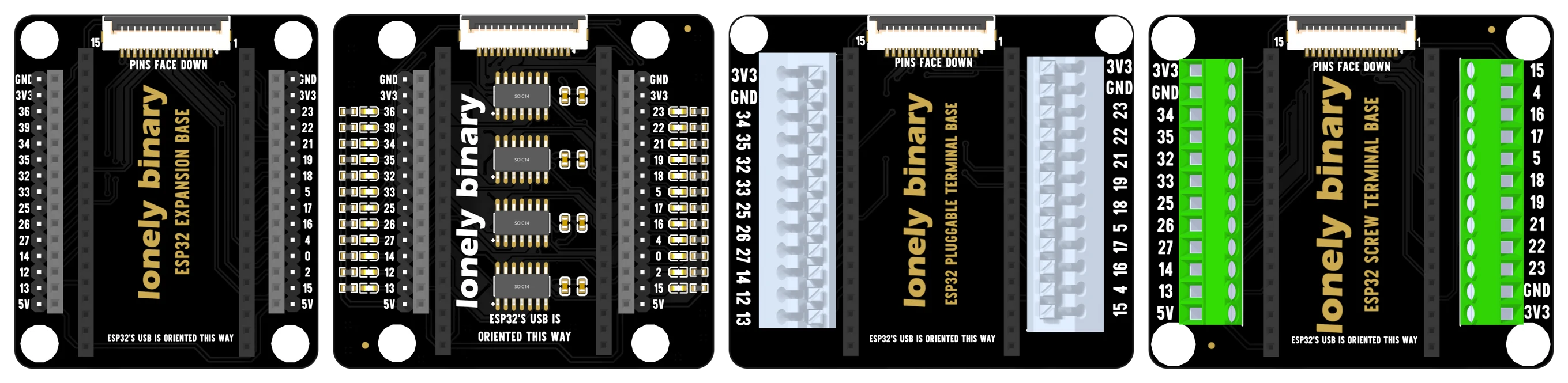
Which one
| Expansion | PinPulse | Pluggable | Screw | |
|---|---|---|---|---|
| A wire lands in | pins and sockets | pins and sockets | a push-in terminal | a screw terminal |
| GPIOs at the edge | 24 | 24 | 20 | 19 |
| 5 V at the edge | yes | yes | no | left block |
| An LED per GPIO | — | yes | — | — |
| Display connector | yes | yes | yes | yes |
| Best for | jumpers, breadboards | debugging, teaching | wiring that changes | wiring that travels |
The two terminal bases are the ones to check against your sketch. They drop GPIO 36 and 39 — input-only pins — and GPIO 0 and 2, which the chip reads while it boots; the screw base drops GPIO 12 as well, and spends the terminal on 5 V.
Wiring, in four lines
- Seat the ESP32 with its USB-C socket over the line reading ESP32'S USB IS ORIENTED THIS WAY. Press straight down, a thumb at each end.
- Plug the USB cable in after the board is seated, never before.
- Take 3.3 volts and a ground from the nearest edge row or terminal; both sides of every base have their own.
- For a display, lift the flap on the fifteen-way socket, slide the ribbon in with its contacts facing the board, and press the flap down.
The boards
Where to start
The handbook below starts with the one mistake that ends a session — the board going in backwards — and then takes each of the four boards in turn. If you already know which one you are holding, jump straight to its chapter.
When it doesn’t work
- Which way round does the ESP32 go?
- USB-C socket over the line printed across the top face of the base, which reads ESP32'S USB IS ORIENTED THIS WAY. The board fits mechanically both ways round, and the wrong way puts its 5 V pin into the socket wired to ground — a short across the USB supply — while the base's 3.3 V rail lands on GPIO 6, a flash pin. Seat the board first, plug the cable in second.
- Which base should I buy?
- Jumper wires and breadboards: the expansion base. Debugging, or teaching somebody what a pin is: the PinPulse, which is the expansion base with an LED on every GPIO. Bare wire you will rewire often: the pluggable terminal base. Bare wire that has to survive being carried: the screw terminal base. The two terminal bases bring out fewer pins — 20 and 19 against 24 — so check your sketch's pin list first.
- Why do the terminal bases have fewer pins?
- Twelve terminals a side is twenty-four terminals, and each block spends two on 3.3 volts and a ground. That leaves twenty places for twenty-four GPIOs. The four both terminal bases drop are GPIO 36 and 39, which are input-only, and GPIO 0 and 2, which are strapping pins the chip reads while it boots. The screw terminal base drops GPIO 12 as well and spends that terminal on a 5 V output.
- Do the LEDs on the PinPulse base interfere with I²C or SPI?
- No, and that is what the four chips are for. Each GPIO drives the input of an SN74HC04 inverter — a CMOS gate that draws at most a microamp — and the LED hangs off the inverter's output, taking its current from the 5 V rail. Your signal is not loaded, so a bus still works with the lights on.
- An LED flickers when I wave my hand near it.
- That pin is floating, and the base says so in silkscreen on its back. A GPIO your sketch has not configured is undriven, not LOW, and the inverter input picks up whatever is in the air. Call pinMode(n, OUTPUT) and write it HIGH or LOW.
- What is the fifteen-way socket for?
- A display on a flat-flex ribbon instead of eight jumper wires. It carries 13 GPIOs plus 3V3 and GND, and the whole pin table is printed on the back of every base. The contacts on the ribbon must face down, towards the board — upside down nothing connects, and nothing is damaged. Which pin carries chip select or backlight is decided by the display module, not by the base.
- There is nothing on the 5V row.
- That row is the dev board's 5V pin, which is USB power one Schottky diode down. With no USB cable there is nothing on it, including when you are powering the board through its 3V3 pin. The pluggable terminal base has no 5 V terminal at all.
- Can I still use a breadboard?
- Yes — jumper from the base's edge to the breadboard. What you no longer have to do is push the ESP32 itself into one, which is the arrangement that leaves a single spare column of holes on one side and none on the other.