The pins that come out
The ESP32 has thirty-two GPIOs. No base brings out more than twenty-four, and the two terminal bases stop at twenty and nineteen. Here is which ones, and why each of the missing is missing.
Thirty-eight pins, twenty-four you can use
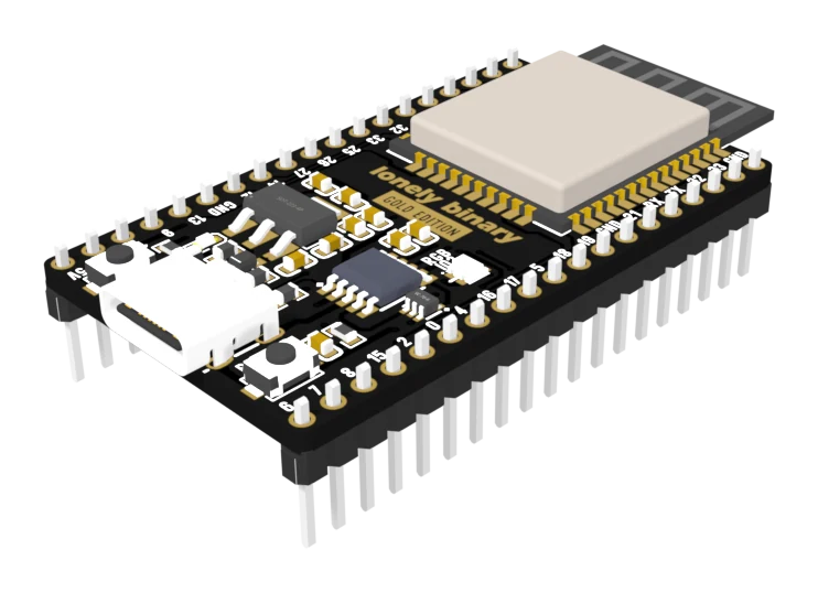
Count the pins on the dev board and you get thirty-eight: thirty-two GPIOs, two supply pins, three grounds and EN. Count the GPIOs at the edge of an expansion base and you get twenty-four.
The eight that never appear are not an omission. Six of them — GPIO 6 to 11 — run to the flash chip inside the module's metal can, where the program you just uploaded lives. A wire on any of those stops the board booting. The other two — GPIO 1 and 3, printed TX and RX — are the serial link your computer programs the board over.
A base that brought those eight out would be selling you eight pins you must not use.
Then the terminal bases drop five more
Twelve terminals a side is twenty-four terminals, and each block spends two of them on 3.3 volts and a ground. That leaves twenty places for twenty-four GPIOs, and something has to go.
| Expansion | PinPulse | Pluggable | Screw | |
|---|---|---|---|---|
| GPIOs at the edge | 24 | 24 | 20 | 19 |
| GPIO 36, 39 | yes | yes | — | — |
| GPIO 0, 2 | yes | yes | — | — |
| GPIO 12 | yes | yes | yes | — |
| 5 V at the edge | yes | yes | — | yes |
The four both terminal bases drop are the four with the most conditions attached anyway:
GPIO 36 and 39 are input-only. They can read a voltage and they can never
drive one. digitalWrite on them does nothing at all.
GPIO 0 and 2 are strapping pins. The chip reads them while it boots to decide whether to run your program or wait for an upload, so anything attached to them has to be quiet for the first quarter of a second.
The screw terminal base drops a fifth, GPIO 12, which is also a strapping pin — and spends the terminal on a 5 volt output instead.
What the display connector reaches
Thirteen of the twenty-four also appear on the fifteen-way display connector, and that is true on all four bases including the terminal ones. GPIO 2 has no terminal on either terminal base, but it does have a pin on the ribbon — so a display can use it even where a screwdriver cannot.
When it does not work
GPIO 6 to 11 are wired to the SPI flash chip inside the module's metal can. They appear on the dev board's own header, and putting anything on one of them stops the chip booting. No base brings them out, which is the base protecting you from the dev board.
They are GPIO 1 and 3, and they are the serial link the USB port programs the board over. No base brings them out either. If you need a second serial port, the ESP32 can put UART1 or UART2 on almost any free GPIO — pick two from the rows that do come out.
GPIO 34, 35, 36 and 39 are input-only on the classic ESP32. No pinMode will make them drive anything. They read voltages perfectly well, which is what they are for.
Those are exactly the five the terminal bases drop, and there is no way to reach them from a terminal. The display connector carries GPIO 0's neighbours but not GPIO 0. Either move the signal to a pin that is brought out, or use the expansion or PinPulse base, which have all twenty-four.
Where the 3.3 and 5 volts come from, and which base has which.
Power out of the base →Edit this page — content/books/esp32-base/the-pins-that-come-out.mdx
Questions about this product
See what other owners have asked, and read their solutions.
This page covers several products. Choose yours to see the right discussions.
Discuss this article
Ask about this page. The answer stays here, on the page it belongs to, for whoever hits the same wall next.