The screw terminal base
Two twelve-way screw blocks, for wiring that has to survive being carried. Nineteen GPIOs, because the twelfth way on the left block is a 5 volt output instead of GPIO 12 — the only 5 volt terminal on any of the four bases.
Wiring that stays put
Same two blocks as the pluggable base, same 3.5 mm spacing, same twelve ways a side — with a screw over each one instead of a spring. A screw terminal is what you want when the thing you are building is going to be picked up, driven somewhere, or left alone for a year.
Strip about 7 mm, back the screw out until you can see the clamp plate lift, put the bare copper under it, and tighten until the wire will not come out by hand. The commonest failure is a screw tightened onto insulation: it feels tight, it tests dead, and it looks perfect.
The twelfth way, and a block printed upside down
The two terminal bases differ by exactly two positions on the left block — and on the right, this board prints the same twelve signals the other way up.
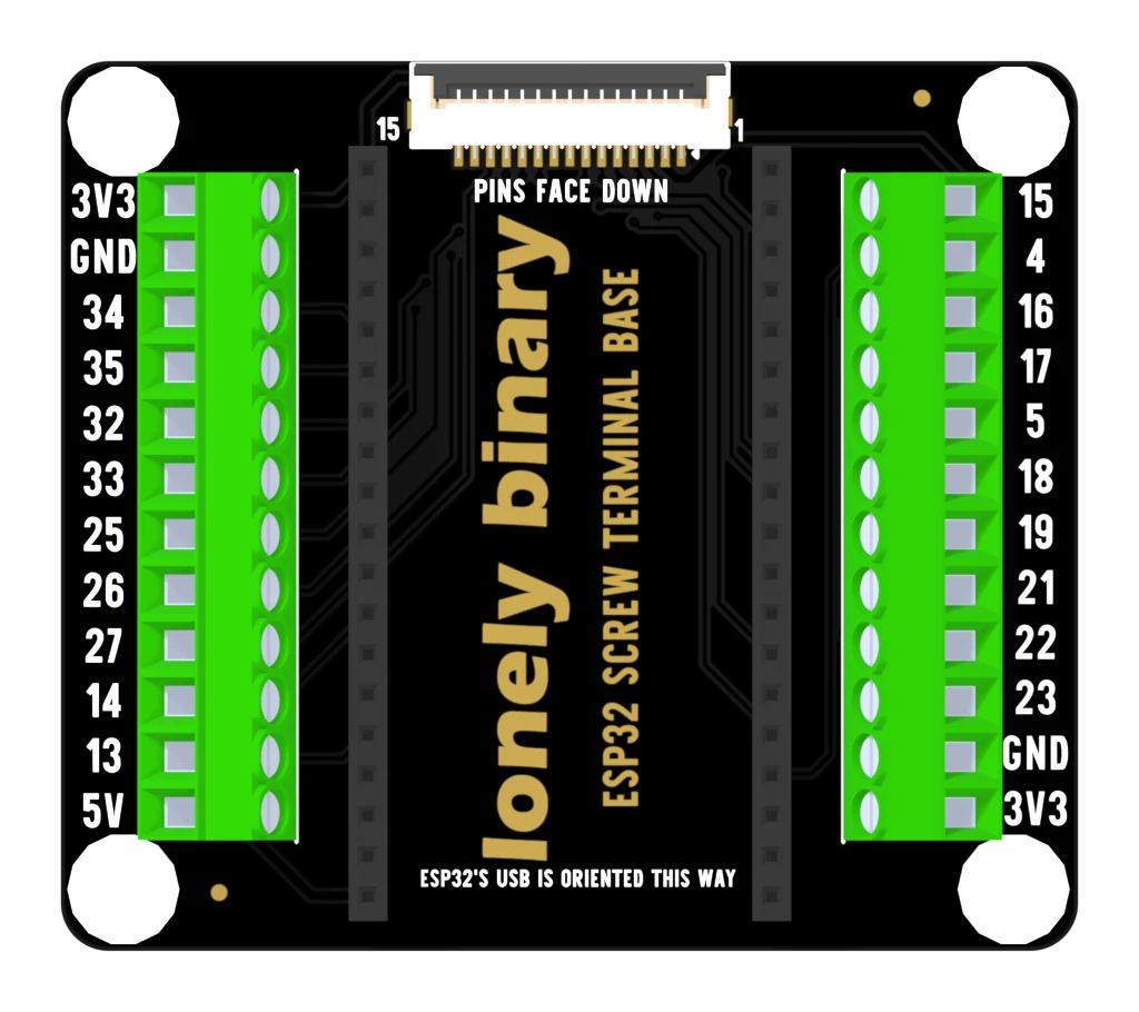
Look at the picture above again: 3V3 and GND are at the top of the left block and at the bottom of the right one. On the pluggable base they are at the top of both. It is the one thing about this board worth checking twice, and the fix is to read the label rather than counting terminals down from a corner.
The left block is the other difference. The pluggable base ends GPIO 12, GPIO 13. This one ends GPIO 13, 5V. So this is the only base of the four that will feed a 5 volt sensor straight out of a terminal, and the only one with no way to reach GPIO 12.
That is a good trade for most builds. GPIO 12 is a strapping pin — the ESP32 reads it while it boots, and a load on it can change what the chip decides to do — so it is the GPIO with the most conditions attached, and 5 volts at a terminal is the thing people actually ask for.
What is on the twelve
Left block, top to bottom: 3V3, GND, then GPIO 34, 35, 32, 33, 25, 26, 27, 14, 13, then 5V. Right block, top to bottom: GPIO 15, 4, 16, 17, 5, 18, 19, 21, 22, 23, then GND and 3V3.
Nineteen GPIOs in total, which is the fewest of the four bases. Which nineteen is the next page.
When it does not work
The clamp has closed on insulation rather than copper, or beside the wire rather than on it. Back the screw right out, look into the terminal to see the clamp plate lift, then insert about 7 mm of bare wire so the plate lands on copper. Tighten until firm, then tug.
The left block spends its last way on 5V instead. GPIO 12 is a strapping pin the chip reads at boot, so it is the one of the twenty-four with the most conditions attached; if your sketch needs it, the expansion or PinPulse base has it. The pluggable terminal base has GPIO 12 and no 5 V.
The same twelve-way arithmetic as the pluggable base. GPIO 36 and 39 are input-only and can never drive anything, and GPIO 0 and 2 are strapping pins. That leaves nineteen GPIOs across the two blocks.
Check the right-hand block. On this board it is printed the other way up from its own left block — 15 at the top and 3V3 at the bottom — so a wire copied across by position lands eleven ways out. The signals and their order along the connector are the same; only the labelling is reversed. Read the label, not the position.
They are small and they do not need much. Tighten until the wire will not pull out by hand and stop there. If a terminal has been over-tightened onto insulation and the thread is damaged, move that signal to a spare way rather than fighting it.
All thirty-eight pins, and which of them each base can reach.
The pins that come out →Edit this page — content/books/esp32-base/the-screw-terminal-base.mdx
Questions about this product
See what other owners have asked, and read their solutions.
This page covers several products. Choose yours to see the right discussions.
Discuss this article
Ask about this page. The answer stays here, on the page it belongs to, for whoever hits the same wall next.