The pluggable terminal base
Two twelve-way push-in blocks instead of pin rows: press the button, push the bare wire in, let go. Twenty GPIOs, a ground and a 3.3 volt supply on each side, and no 5 volt terminal.
No jumper wires at all
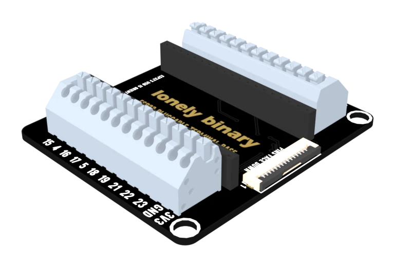
This base replaces both edge rows with a twelve-way push-in terminal block on each side. A wire goes in as bare copper and is held by a spring, so there is nothing to solder, nothing to crimp and nothing to tighten.
Press, insert, release
The order matters, and the middle step is the one people skip.
Strip about 9 mm — a little more than the depth of the block, a little less than anything that would leave copper in the open. Press the button above the hole, push the wire in until it stops, then let go. Tug it afterwards. A wire that moves never reached the busbar, and a connection that is nearly made is worse than one that is obviously not, because it works on the bench and fails in the box.
What is on the twelve
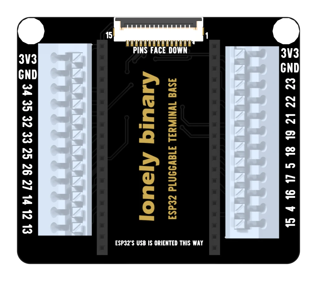
Left block, top to bottom: 3V3, GND, then GPIO 34, 35, 32, 33, 25, 26, 27, 14, 12 and 13. Right block: 3V3, GND, then GPIO 23, 22, 21, 19, 18, 5, 17, 16, 4 and 15.
Twenty GPIOs, against twenty-four on the two 2.54 mm bases. GPIO 36, 39, 0 and 2 have no terminal — the pin page has the whole comparison — and neither does 5 volts.
That last one catches people. Both blocks give you 3.3 volts and a ground, and that is all the power this base hands out. A 5 volt sensor wired to this base needs its own supply, with its ground joined to the board's.
When to reach for it
When the wiring will change. Push-in terminals take a wire out as easily as they take it in, which makes this the base to build a prototype on that is going to be rewired six times before it is right — and to hand to somebody who has never used a screwdriver on electronics.
When the wiring will stop changing, and especially when it will be carried somewhere, the screw terminal base is the one that holds.
When it does not work
Press and hold the button above the hole first. The spring inside is closed until you do, and pushing harder against a closed spring bends the copper rather than opening it. Press, insert, release, then tug the wire — if it comes out, it never reached the busbar.
There is not one on this base. Twelve ways a side went on 3V3, a ground and ten GPIOs, and the 5 volt pin was the one left out. A 5 volt sensor needs its own supply with its ground joined to the board's; the screw terminal base is the one that brings 5 V out to a terminal.
Twenty GPIOs fit in twenty-four terminals once each block has spent two on power, and these four are the ones that were dropped. GPIO 36 and 39 are input-only and can never drive anything; GPIO 0 and 2 are strapping pins the chip reads while it boots, so they are the fussiest to use anyway. The expansion and PinPulse bases have all four.
Twist the strands between finger and thumb before inserting, or fit a ferrule. A stray strand outside the block is 3.5 mm from the next terminal, which is close enough to matter.
The same blocks with screws, one GPIO fewer, and 5 volts instead.
The screw terminal base →Edit this page — content/books/esp32-base/the-pluggable-terminal-base.mdx
Questions about this product
See what other owners have asked, and read their solutions.
This page covers several products. Choose yours to see the right discussions.
Discuss this article
Ask about this page. The answer stays here, on the page it belongs to, for whoever hits the same wall next.