The display port
A fifteen-way ribbon socket on the top of every base, carrying thirteen GPIOs, a 3.3 volt rail and a ground. The pin table is printed on the back of the board, and the contacts face down.
Fifteen ways instead of eight wires
Every one of the four bases carries the same connector on its top face: a fifteen-way flat-flex socket on a 1.0 mm pitch, up near the antenna end of the board.
Thirteen of the fifteen are GPIOs — 32, 4, 2, 19, 18, 23, 15, 33, 25, 26, 27, 21 and 22 — and the other two are a ground and 3.3 volts. Every one of those GPIOs is the same net as its row at the edge, so a display on the ribbon and a jumper on the edge row are the same wire, and two things driving it are two things fighting.
The table is on the back
You do not have to remember any of that. The back of every base prints it:
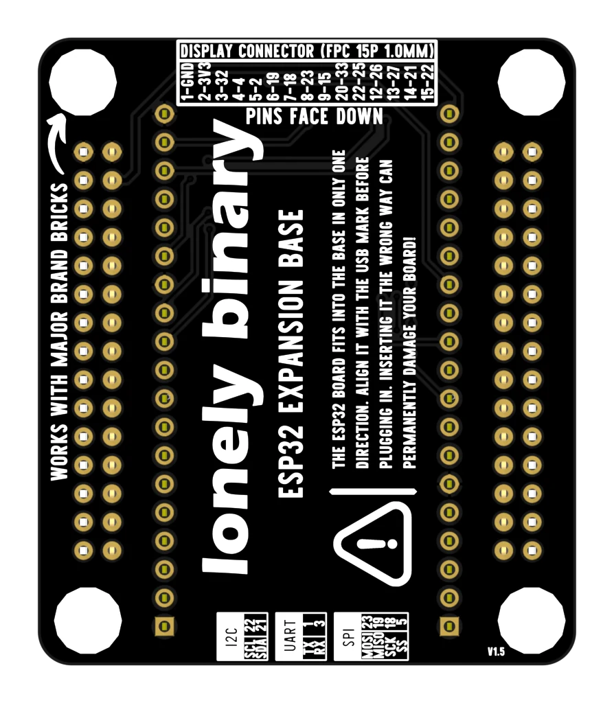
Two warnings about the small print at the bottom of that picture. The I2C and SPI boxes name the ESP32's default pins, and all of those do reach the edge. The UART box names GPIO 1 and 3, and those two reach nothing: they are the serial link your computer uploads over, and no base brings them out.
Getting the ribbon in
The socket has a dark flap across the back of it. Lift the flap, slide the ribbon in square until it stops, then press the flap down.
The contacts on the end of a flat-flex ribbon are on one face only, and this socket wants them facing down, towards the board. The words are printed next to the socket for that reason. Upside down, nothing connects and nothing is harmed — which is why "the display does nothing at all" is nearly always this and not a wiring fault.
What it is for
A single ribbon instead of eight jumper wires to a screen. Which pin does what is decided by the module on the other end, not by the base — so the thing to read next is that module's own pinout, not this one.
When it does not work
Check which way up the ribbon went. The board says PINS FACE DOWN beside the socket: the shiny contacts on the end of the ribbon must face the PCB, with the stiffener facing you. Upside down, all fifteen ways make no contact at all and nothing is damaged — it simply does nothing.
The ribbon is not fully home. Lift the dark flap at the back of the socket all the way up, slide the ribbon in square until it stops, then press the flap down. Forcing the flap onto a half-inserted ribbon bends the contacts.
The base does not decide that. It brings thirteen GPIOs to a connector; which of them carries chip select, data/command, reset or backlight is decided by the display module at the other end of the ribbon, and only that module's own documentation knows. The base's job is the wiring, not the protocol.
Only from the 3.3 volt pin, which is the dev board's regulator output shared with the radio. There is no 5 V on the connector. A panel with a hungry backlight wants its own supply.
They run 15 on the left and 1 on the right, as the board prints them. Pin 1 is GND and pin 2 is 3V3, which is the end nearest the right-hand edge of the board when you are looking at the top with the labels the right way up.
One sketch, four bases, and the one where you need nothing else.
Blink on a base →Edit this page — content/books/esp32-base/the-display-port.mdx
Questions about this product
See what other owners have asked, and read their solutions.
This page covers several products. Choose yours to see the right discussions.
Discuss this article
Ask about this page. The answer stays here, on the page it belongs to, for whoever hits the same wall next.