The expansion base
The plain one: two rows of 2.54 mm contacts down each edge, one of pins and one of sockets, so a jumper fits whichever end it happens to have. All twenty-four available GPIOs, and the display port.
Fifteen rows a side
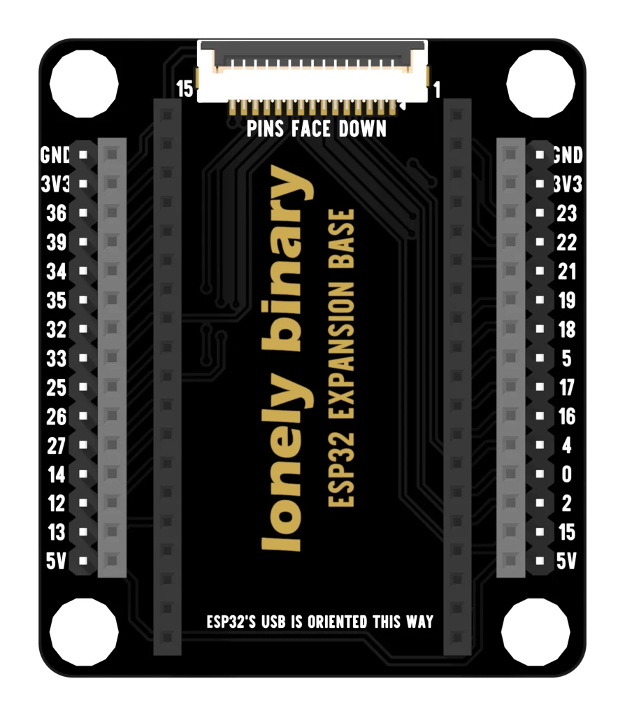
The edge is fifteen contacts on each side, printed top to bottom. On the left: GND, 3V3, then GPIO 36, 39, 34, 35, 32, 33, 25, 26, 27, 14, 12, 13, then 5V. On the right: GND, 3V3, then GPIO 23, 22, 21, 19, 18, 5, 17, 16, 4, 0, 2, 15, then 5V.
Twelve GPIOs a side, twenty-four in all, with a ground and both supply rails at the ends of each row so nothing has to reach across the board.
One row, three places
Each row is one net. Follow it and it reaches two contacts at the edge, the socket pin the ESP32 sits on, and — for thirteen of the twenty-four GPIOs — a pin of the display connector as well.
That is worth understanding before you wire anything, because it is also the rule for what you may not do. Two sensors reading the same row is fine. Two things driving it is two outputs fighting, and the row has no idea they arrived through different holes.
Two rows, two kinds of jumper
A jumper wire ends in either a plug or a socket, and which one you are holding usually decides how much of the evening you spend hunting for an adapter. This base carries a row of each on every side, at the same fifteen positions, so whichever end you have goes straight on.
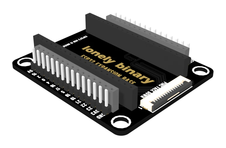
The spacing is 2.54 mm, so a breadboard jumper reaches everything and a ribbon cable with a 0.1 inch connector lands square.
What it does not have
No LEDs, no buffers, no regulator — this board is copper. Everything at the edge is the ESP32's own pin, and the 3.3 volts is the dev board's own regulator output. If you want to see what the pins are doing, that is the next board.
When it does not work
Whichever end your jumper has. The two rows on one side are the same copper as each other and as the socket pin under the board, so there is no electrical difference — only a mechanical one. Use the socket row for a jumper with a plug on the end and the pin row for one with a socket on the end.
That is allowed, and often useful: one sensor's signal and one meter probe on the same GPIO. What is not allowed is two things driving it. Two outputs on one row is two chips fighting, and the row does not care that they arrived by different holes.
No base brings those out. GPIO 6 to 11 are wired to the flash chip inside the module's can, and GPIO 1 and 3 are the serial link your computer programs the board over. The pins exist on the dev board; using them stops it booting or stops it uploading.
The two rows of edge contacts stand proud of the PCB and the corners have nothing under them. Four rubber feet in the mounting holes, or a brick under each corner, and it sits flat.
The same board with an LED on every pin, and nothing added to your signals.
The PinPulse base →Edit this page — content/books/esp32-base/the-expansion-base.mdx
Questions about this product
See what other owners have asked, and read their solutions.
This page covers several products. Choose yours to see the right discussions.
Discuss this article
Ask about this page. The answer stays here, on the page it belongs to, for whoever hits the same wall next.