The PinPulse base
The expansion base with an LED on every one of the twenty-four GPIOs. Four inverter chips drive them from the 5 volt rail, so the lights cost your signals a microamp and an I²C bus still works with them on.
Twenty-four lights
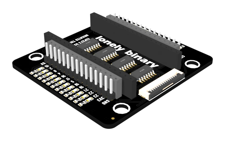
The PinPulse base is the expansion base with a column of LEDs added outboard of each edge row: one for every GPIO the base brings out, twenty-four in all. Each one is lit while its pin is HIGH.
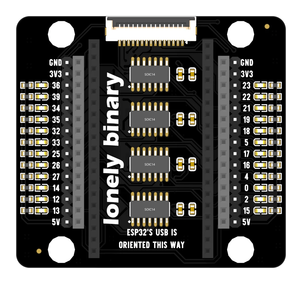
That is genuinely useful and slightly suspicious at the same time. An LED needs current, current on a signal line changes the signal, and a base that quietly loaded twenty-four pins would be worse than no base at all.
Where the current comes from
It does not come from your pin. Each GPIO goes to the input of one channel of a SN74HC04 — a six-channel inverter — and the LED hangs off that channel's output, with a 5.1 kΩ resistor up to the 5 volt rail.
An inverter input is a CMOS gate: a few picofarads, and a leakage current the datasheet caps at one microamp. So the pin drives a capacitor the size of a short jumper wire and nothing else, while the light is paid for out of the 5 volt rail. An I²C bus, an SPI clock and a WS2812 data line all keep working with the lights on, which is exactly what the four chips are there to buy.
The inverter is also why HIGH lights the LED: the output goes LOW, and that is the end of the LED with somewhere to go.
The floating pin
The back of the board carries this, and it is the most useful sentence printed on any of the four bases:
By default, GPIO pins are in a floating state, so touching them with your finger can change their state and make the LED blink. To fix this, set the pinMode to output and specify HIGH or LOW.
A pin your sketch has not configured is not LOW. It is undriven, its inverter input is listening, and the LED is reporting the truth. Set the pin and the flicker stops.
Two of the twenty-four are worth knowing about in advance. GPIO 36 and 39 are
input-only on the ESP32 — no digitalWrite will ever light them, and their
LEDs show what your circuit is putting on them, which is the whole point of
having an LED on an input.
When to reach for it
For debugging, and for teaching. If the question is "is the pin doing anything", this board answers it without a meter, a scope or a second LED in your hand. Everything else on it is the expansion base, so nothing you learn here has to be unlearned on the other three.
When it does not work
That pin is floating — nothing in your sketch has claimed it — and the base says so on its back. A CMOS input with nothing driving it picks up whatever is in the air, including you. Call pinMode(n, OUTPUT) and digitalWrite it HIGH or LOW and it will stop.
The chips run from the 5 volt rail, which is the dev board's 5V pin — that is USB power. Running the board from its 3V3 pin instead leaves the inverters unpowered and every LED off. Plug the USB cable in.
A misprint in the silkscreen on the back of the V1.5 board. It is the same board as the one on the box and in this handbook; nothing about it is different.
No, and that is the reason for the chips. Each LED hangs off an inverter output, not off your pin, so GPIO 0 sees an input that draws a microamp at most and the bootloader reads it exactly as it would with nothing attached.
The inverters are SN74HC04, and TI guarantees a HIGH is read as a HIGH at 0.7 of the chip's supply — 3.15 V on a 4.5 V rail. The base runs them from the ESP32's 5V pin, so a 3.3 V output sits close to that guarantee rather than well above it. In practice these inputs switch near half the supply and all twenty-four light. If you are feeding the 5V pin from a bench supply at a full 5 volts rather than from USB, the threshold rises with it, and that is the first thing to change.
Each one is fed through 5.1 kΩ, which is about half a milliamp — bright enough to read indoors and dim enough that all twenty-four together stay under fifteen milliamps. They are indicators, not lighting.
No screwdriver, no jumper wires: a spring holds the bare wire.
The pluggable terminal base →Edit this page — content/books/esp32-base/the-pinpulse-base.mdx
Questions about this product
See what other owners have asked, and read their solutions.
This page covers several products. Choose yours to see the right discussions.
Discuss this article
Ask about this page. The answer stays here, on the page it belongs to, for whoever hits the same wall next.