A 5 V I²C screen on an ESP32
An LCD1602 with an I²C backpack wants 5 V, and its pull-up resistors put that 5 V on the bus. A 2CH board between it and an ESP32 takes three power wires and two signal wires, and a scan proves it works in ten seconds.
Why this screen needs a converter
The LCD1602 needs 5 V to show anything, and its I²C backpack has pull-up resistors to that same 5 V. So SDA and SCL sit at 5 V whenever the bus is idle. Your sketch does not send that 5 V. The screen puts it there by itself.
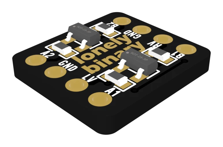
What goes where
| From | To |
|---|---|
| ESP32 3V3 | 2CH LV |
| ESP32 5V | 2CH HV, and backpack VCC |
| ESP32 GND | 2CH GND, and backpack GND |
| ESP32 SDA | 2CH A1 |
| ESP32 SCL | 2CH A2 |
| 2CH B1 | backpack SDA |
| 2CH B2 | backpack SCL |
Which GPIOs are SDA and SCL depends on your ESP32. The sketch below prints them.
Scan the bus
Upload the sketch and open the serial monitor at 115200. It prints the two pins, then every address that answers, every three seconds. An LCD backpack normally answers at 0x27 or 0x3F.
Finding the address proves more than it seems. Each answer is the screen pulling a line LOW back through the converter, so both directions work.
Then print something
Any I²C LCD library from the Library Manager will take the address you just found. If the screen lights but shows only blocks, turn the contrast potentiometer on the back of the backpack.
The code
A bus scan, and nothing else. It prints which GPIOs your ESP32 uses for SDA and SCL, so you know where A1 and A2 go, then lists every address that answers. An LCD backpack usually answers at 0x27 or 0x3F.
// Converter wiring for this sketch (2CH board).
//
//   ESP32 3V3  -> LV
//   ESP32 5V   -> HV, and the LCD backpack's VCC
//   ESP32 GND  -> GND, and the backpack's GND
//   ESP32 SDA  -> A1      B1 -> backpack SDA
//   ESP32 SCL  -> A2      B2 -> backpack SCL
//
// Arduino IDE: any ESP32 board. Tools settings as you normally use them —
// this sketch needs no library and no special options.

#include <Wire.h>

void setup() {
  Serial.begin(115200);
  delay(500);
  Wire.begin();
  // SDA and SCL are your board's default I2C pins. Wire A1 and A2 to these.
  Serial.printf("SDA is GPIO %d, SCL is GPIO %d\n", SDA, SCL);
}

void loop() {
  int found = 0;
  for (uint8_t addr = 1; addr < 127; addr++) {
    Wire.beginTransmission(addr);
    if (Wire.endTransmission() == 0) {
      Serial.printf("found a device at 0x%02X\n", addr);
      found++;
    }
  }
  if (found == 0) Serial.println("nothing answered - check LV, HV and GND first");
  Serial.println();
  delay(3000);
}
If it prints “nothing answered”, the fault is the wiring, not the sketch — check LV, HV and GND with a meter before anything else. If it finds an address, the converter is working in both directions: the scan only succeeds when the screen can pull a line LOW back through it.
When it does not work
Check in this order: LV at 3.3 V and HV at 5 V with a meter, GND shared, then SDA and SCL not swapped between A1 and A2. Make sure it is a MOSFET board or a TXS — a TXB will not pass I²C. And confirm the backpack is getting 5 V on its VCC pin.
The bus is fine; that is the screen's contrast. Turn the small potentiometer on the back of the backpack slowly with a screwdriver until characters appear. It is the commonest problem with these screens and has nothing to do with the converter.
An intermittent bus is almost always a loose ground or a long wire. Check that the GND wire really connects both boards, and keep the I²C wires short. On a breadboard, press the converter's pins firmly home.
No. The backpack has pull-ups on the 5 V side, and the 2CH board has a 10 kΩ pull-up on each side of both channels.
The other common build: one channel of a TXB0108 and a rainbow.
An LED strip from a 3.3 V pin →Edit this page — content/books/llc/a-5v-screen-on-an-esp32.mdx
Questions about this product
See what other owners have asked, and read their solutions.
This page covers several products. Choose yours to see the right discussions.
Discuss this article
Ask about this page. The answer stays here, on the page it belongs to, for whoever hits the same wall next.