One transistor, two resistors
Each channel of the 2CH, 4CH and 6CH boards is one BSS138 transistor and two 10 kΩ resistors. Three situations explain everything it does, including why it needs no direction pin.
The parts
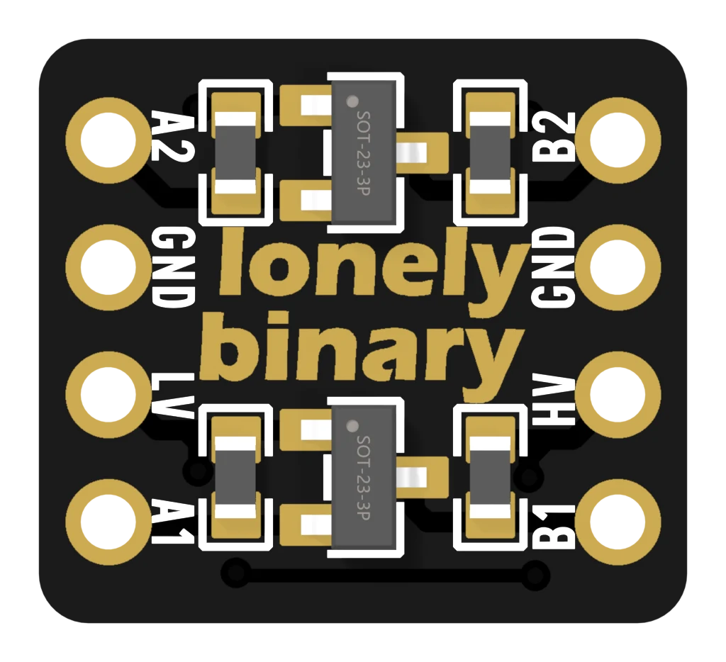
A transistor here is a switch worked by voltage. Its gate is tied to LV. When the gate is a few volts above the A-side pin, the switch closes and joins A to B. When the two are equal, it stays open.
Each side also has a 10 kΩ pull-up resistor to its own supply. It holds that side HIGH whenever nobody is pulling it down.
The three situations
Pick one and step through it:
Both sides idle HIGH. Now the 3.3 V board pulls A1 low.
- Nobody talking. Each resistor holds its side HIGH: 3.3 V on A, 5 V on B. The transistor stays off.
- The 3.3 V side pulls LOW. A drops to 0 V, the gate is now 3.3 V above it, and the transistor switches on. B follows A down.
- The 5 V side pulls LOW. The transistor is off, but the diode built into it lets A fall to about 0.6 V. That is enough for the gate to switch the transistor on, and A goes fully LOW.
The third one is the clever part. It is why the same channel works in both directions without being told which way.
What the design costs
Nobody ever drives a HIGH on this board. The resistors make every HIGH, and a resistor is slow to fill a wire. That sets a speed limit — the slow rising edge shows exactly where.
It also means a HIGH is weak: half a milliamp through 10 kΩ. Plenty for a signal, nothing like enough for an LED.
Why it suits I²C
I²C already works this way. Resistors hold both lines HIGH, and devices only ever pull them LOW. The MOSFET board fits that pattern exactly, which is why eighteen of the twenty-seven boards are 2-channel: one for SDA, one for SCL.
When it does not work
That is the transistor's built-in diode conducting on its own. It happens when the 5 V side is holding the line LOW and LV is not connected, so the transistor cannot switch properly. Check the LV wire.
No. The board has a 10 kΩ pull-up on each side of every channel, and most I²C modules bring their own as well. Together they are fine for a normal bench setup.
They are built and sold for 3.3 V to 5 V. At 1.8 V the transistor's gate is close to the voltage it needs just to switch, which is where it stops being dependable. The TXB0108 and TXS0108 are rated down to 1.2 V and 1.4 V on their A side — use one of those.
Two chips on one footprint. One pushes signals and cannot stand pull-up resistors; the other has them built in.
TXB and TXS: same shape, opposite rules →Edit this page — content/books/llc/one-transistor-two-resistors.mdx
Questions about this product
See what other owners have asked, and read their solutions.
This page covers several products. Choose yours to see the right discussions.
Discuss this article
Ask about this page. The answer stays here, on the page it belongs to, for whoever hits the same wall next.