Power before signals
LV, HV and GND go in before any signal wire, and each of the three fails in its own way when it is missing. On the TXB and TXS boards there is a fourth pin, and the right thing to do with it is nothing.
Three wires, in this order
- LV (VA on the TXB and TXS) to the 3.3 V board's 3V3 pin.
- HV (VB) to the 5 V part's supply.
- GND to the ground of both boards.
Only then the signal wires. Try leaving each power wire out:
No LV: the converter has no idea what 3.3 V is, and nothing useful crosses. No HV: there is nothing to lift a HIGH up to. No GND: the worst, because it half works. Voltage is always measured against ground, and two boards with separate grounds disagree about where zero is.
LV must be the lower one
The A side is the low side on every board. Swap LV and HV and the A pins — the ones connected to your 3.3 V board — sit at 5 V, which is exactly what the converter was meant to prevent.
The MOSFET boards
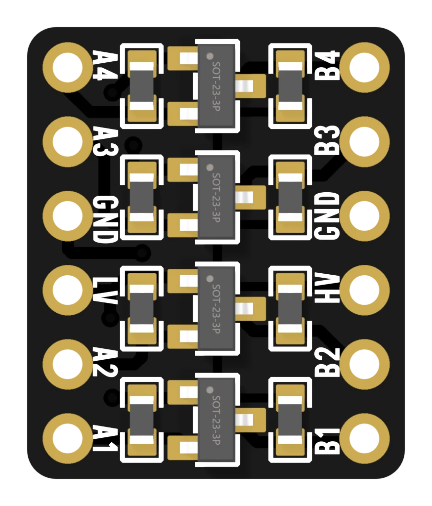
GND appears on both sides and is one connection. So the converter also joins the grounds of your two boards, as long as both are wired to it.
The TXB and TXS boards
These have one GND pin, bottom right on the B side. The pin opposite it, bottom left, is OE: an on/off switch for all eight channels. It is easy to wire as a second ground, and that switches the whole chip off.
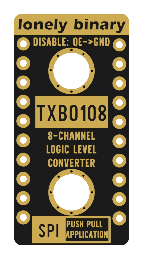
The board already connects OE to VA through a 10 kΩ resistor, so an unconnected OE means on. Leave it alone unless you want a GPIO to switch the converter on and off.
When it does not work
Measure before you rewire. Black probe on GND, red on LV: it should read 3.3 V. Red on HV: 5 V. A zero means that wire is not really connected — a breadboard hole that missed, or a jumper in the wrong row. Check it with a meter walks through all six readings.
Both sides need their supply, and both boards need a shared ground. If each board was powered from its own USB cable, the GND wire through the converter is the only thing joining them — check that it is really there, not just two boards that happen to share a computer.
Nothing is damaged. OE low is an ordinary off state, not a fault. Take the wire off and the board's own pull-up resistor switches the chip back on.
Most development boards have a pin labelled 5V or VIN that carries the USB's 5 V when the board is powered over USB. Check your board's pinout to be sure. The 3V3 pin is the one for LV.
What is inside each channel of the MOSFET boards, and the trick that makes it work in both directions.
One transistor, two resistors →Edit this page — content/books/llc/power-before-signals.mdx
Questions about this product
See what other owners have asked, and read their solutions.
This page covers several products. Choose yours to see the right discussions.
Discuss this article
Ask about this page. The answer stays here, on the page it belongs to, for whoever hits the same wall next.