Which board for which job
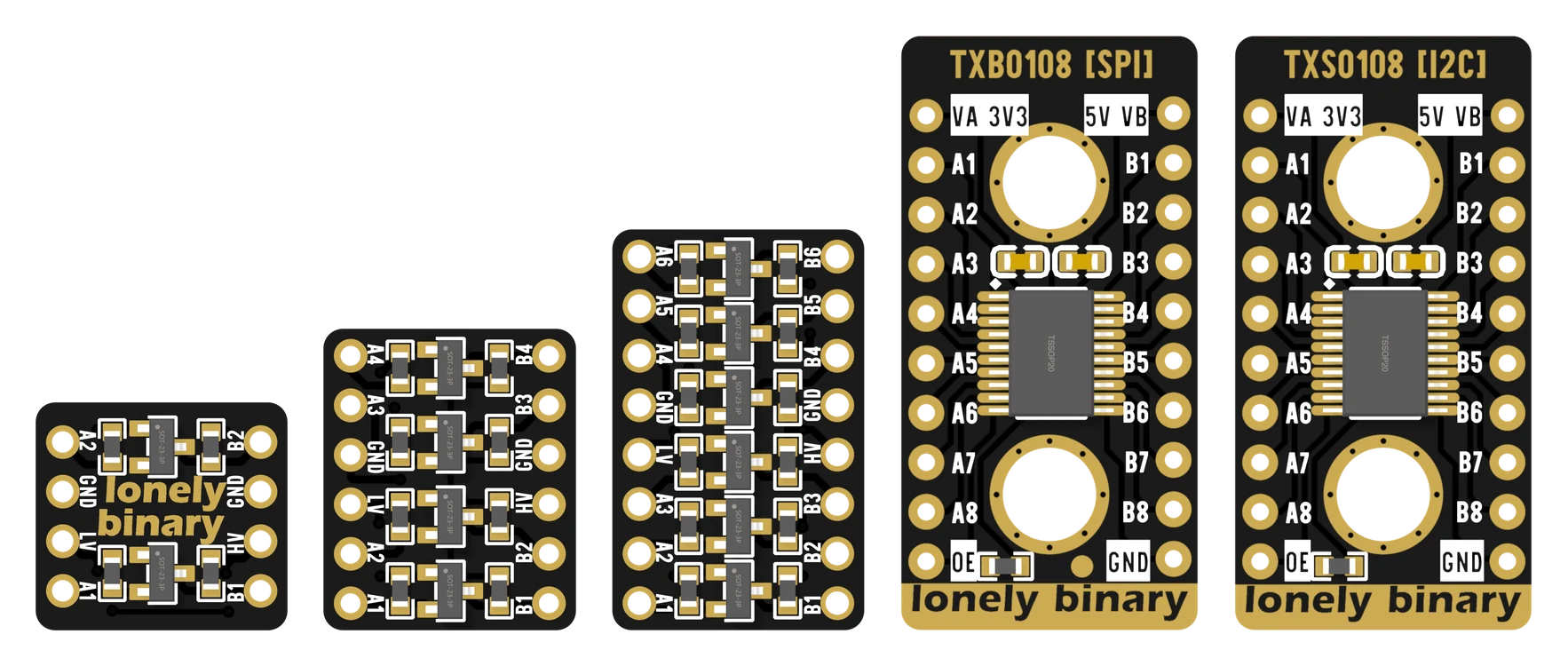
Two questions decide it: does the signal rely on a pull-up resistor, and is it fast? The chooser and the table answer them for the six things people actually connect.
Two questions
- Is the line held HIGH by a resistor? I²C, 1-Wire and a button all are. That rules out the TXB0108.
- Is it fast? SPI and LED strip data are. That rules out the MOSFET boards, or at least makes them a gamble.
The TXS0108 passes both questions, which makes it the safe default when you are unsure. The other two are each the best choice for their own job.
The whole table
| Connecting | MOSFET 2/4/6CH | TXS0108 | TXB0108 |
|---|---|---|---|
| I²C sensor or screen | yes | yes | no |
| Serial (UART) | yes | yes | yes |
| SPI display or SD card | slow clocks only | yes | yes |
| WS2812 LED strip | marginal | yes | yes |
| DS18B20 (1-Wire) | yes | yes | no |
| Button or switch | yes | yes | no |
Mixing boards in one project
Nothing stops you using two. A 2CH for an I²C screen and a TXB for an LED strip can sit on the same breadboard, sharing the same 3.3 V, 5 V and ground rails. Each board still needs its own LV, HV and GND wires.
When it does not work
Ask the two questions. Is the line held HIGH by a resistor, with devices only pulling it LOW? Then not the TXB. Is it faster than a few hundred kHz? Then not the MOSFET board. A slow PWM signal to a motor driver, for example, is driven both ways and slow, so any board will do.
Do not try to make it work. TI's datasheet rules the TXB out for I²C, and a bus that half works is harder to debug than one that does not work at all. A 2-channel MOSFET board is the right part, and there are eighteen in the 27-pack.
No. These boards are for digital signals only. Through a TXB or TXS an analog voltage becomes a 0 or a 1, and through a MOSFET channel it gets distorted. To scale an analog 0–5 V down to 0–3.3 V, use a voltage divider.
The commonest build in this book, from wiring to a working bus scan.
A 5 V I²C screen on an ESP32 →Edit this page — content/books/llc/which-board-for-which-job.mdx
Questions about this product
See what other owners have asked, and read their solutions.
This page covers several products. Choose yours to see the right discussions.
Discuss this article
Ask about this page. The answer stays here, on the page it belongs to, for whoever hits the same wall next.