Check it with a meter
Six readings with a multimeter tell you whether a converter is powered, the right way round and passing signals — before you suspect the sketch, the library or the part on the other side.
Before you start
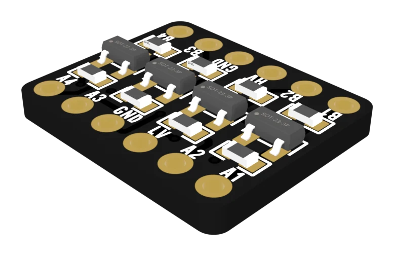
Power both boards as normal. Set the meter to DC volts. The black probe goes on GND and stays there. On the TXB and TXS, that is the one GND pin, bottom right.
Power first
- LV (or VA): 3.3 V.
- HV (or VB): 5 V.
Anything else, stop and fix it — no signal test means anything until both are right.
Idle channels
On the MOSFET boards and the TXS, pull-up resistors hold each side of an idle channel at its own voltage: A1 reads 3.3 V, B1 reads 5 V. On the TXB, an idle channel can read anything. That is not a fault.
Drive a channel
This is the test that works on every board. Unplug A1 from your 3.3 V board first, so you are not shorting its pin. Then:
- Tie A1 to GND. B1 should read 0 V.
- Tie A1 to 3V3. B1 should read 5 V.
If every reading is right and it still fails
Then the converter is wired correctly, and the problem is somewhere else. The usual suspects: a TXB on an I²C bus (TXB and TXS), a fast signal on a MOSFET board (the slow rising edge), or the sketch itself.
When it does not work
LV and HV are swapped. Unplug the power now: the A side is putting 5 V on your 3.3 V board's pins. Swap the two wires, then check the 3.3 V board still works.
The 5 V side is holding the line LOW and LV is missing, so only the diode inside the transistor is conducting. Check the LV wire.
That is normal. The TXB has no pull-ups, so a channel with nothing connected holds whatever level it last had. Test a TXB by tying A1 to GND or 3V3 and reading B1.
Check OE first. If it is wired to GND, every channel is off. Then check that VA and VB are both there — either chip switches its outputs off when a supply is at 0 V.
The specs for all five boards, the table of which board for which job, and the questions people ask first.
Back to the reference →Edit this page — content/books/llc/check-it-with-a-meter.mdx
Questions about this product
See what other owners have asked, and read their solutions.
This page covers several products. Choose yours to see the right discussions.
Discuss this article
Ask about this page. The answer stays here, on the page it belongs to, for whoever hits the same wall next.