Powering the board
Two USB-C sockets, a 5V pin and a 3V3 pin all reach the same rail by different roads. Which road you take decides what the regulator sees, how much of it is wasted as heat, and whether anything at all is standing between your wiring and the board.
Four doors onto one rail
Everything on this board runs from 3.3 V, and there is exactly one thing making it: an AMS1117-3.3 regulator near the middle of the board. Every way of powering the board is a way of feeding that regulator — or of stepping around it.
Reading it from the outside in:
- Either USB-C socket. Each has its own series Schottky diode, and both land on the same 5 V rail. This is what the board is designed for and what every other article in this book assumes.
- The 5V pin on the header. It is on that same rail, one node away from the regulator's input, with nothing in front of it.
- The 3V3 pins on the header. These are the regulator's output. Feeding them means the regulator is not in the circuit at all.
Pick one. The diodes mean a USB cable left plugged in while you feed the 5V pin is tolerated — current cannot flow back out of a socket the way it came in — but that stops being true in the two cases below, and it is not a habit worth having.
The 5V pin
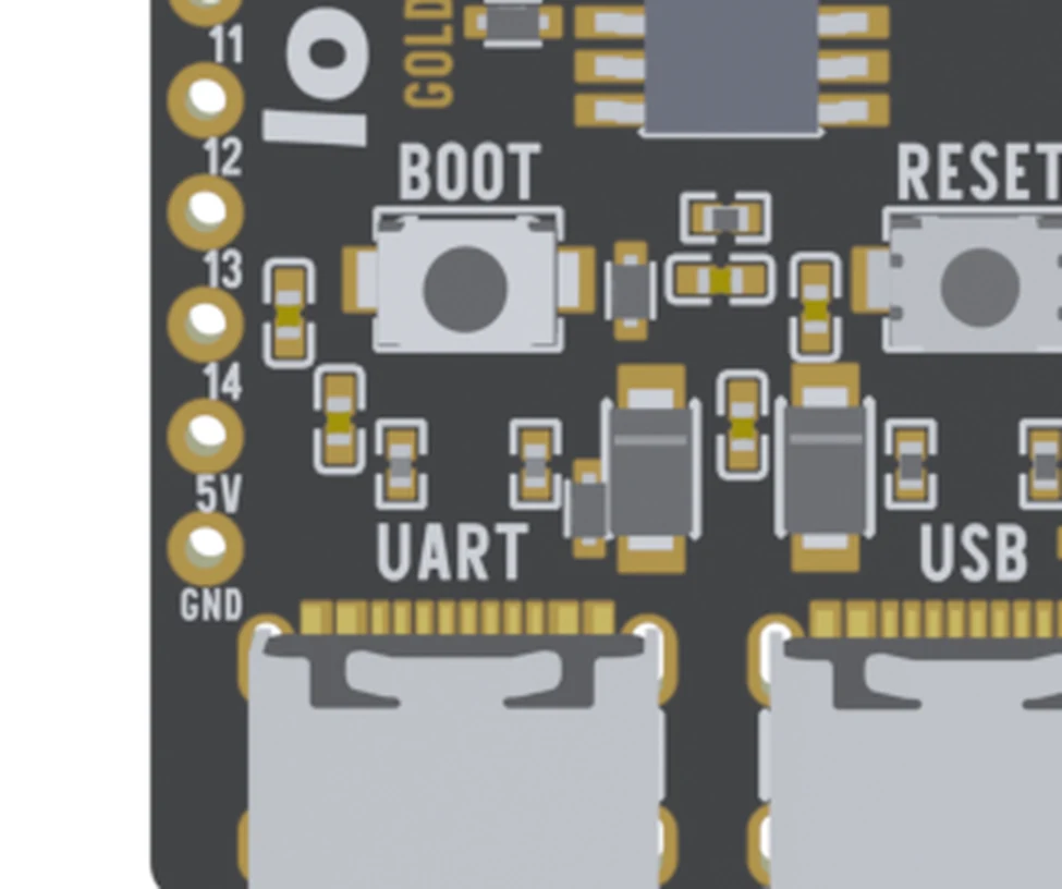
Yes, you can power the board here. The 5V pin and the ground pin beside it are the intended second way in, and a board that runs from USB will run from them.
Three things about it are worth knowing before you wire anything.
It reads about 4.6 V when a USB cable is in. The socket's series Schottky costs three or four tenths of a volt and the pin sits behind it. That is the number to expect, not a fault.
It has no reverse-polarity protection. The diodes protect the sockets, and this pin is downstream of them. Five volts and ground the wrong way round here goes straight into the regulator and the capacitors on the rail. This is the one real hazard of the 5V pin, and it is worth a second look at the wires before the first power-up.
It is a 5 V pin, not a Vin pin. An Arduino Uno's barrel jack takes 7 to 12 V because there is a regulator behind it sized for the job. This one is a small linear part in a SOT-223 package, and a linear regulator turns every volt above 3.3 into heat. At 5 V in and 300 mA out that is half a watt, which is fine. At 12 V in it is over two and a half watts, which is not. Feed it 5 V, give or take half a volt.
The 3V3 pins
The two 3V3 pins at the far end of the same header are the regulator's output. Feeding 3.3 V into them powers the module, the CH340K and the LED directly, and the AMS1117 sits there doing nothing.
That is the efficient option, and the exposed one. A linear regulator throws away a third of what you put in; a 3.3 V supply of your own does not. In exchange:
- 3.6 V is an absolute maximum, not a guideline. The module is a 3.3 V part. A lithium cell at 4.2 V on this pin does not damage the regulator — it damages the chip.
- Do not do it with a USB cable plugged in. Two supplies would then be holding one node, one of which cannot be turned down.
- Nothing protects this pin either. Same as the 5V pin, minus the regulator that would otherwise absorb the mistake.
A 3.7 V lithium cell fits neither pin: too low for the regulator, too high for its output. It needs a boost converter into the 5V pin, or its own 3.3 V regulator into the 3V3 pin. Battery and power budget works the sums.
The solder pad on the back
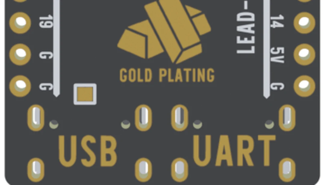
The pad joins the USB socket's 5 V line to the board's 5 V rail. Bridged, the two sockets share one rail, and a charger on the UART socket can then power a USB device plugged into the USB one — which is the whole point of it, and The two USB-C ports covers that trade in full.
One consequence belongs here rather than there, because it only bites people who use the 5V pin:
When USB works and the 5V pin does not
This is the commonest support email about the 5V pin, and the board is almost never the fault. In order of how often it turns out to be the answer:
The supply sags. A linear regulator needs its input to stay above 3.3 V plus its own dropout, and that dropout grows with current — around six tenths of a volt at idle, a little over a volt near an amp. A Wi-Fi transmit burst pulls a few hundred milliamps for a few milliseconds. If the voltage at the pin dips below the floor during that burst, the rail sags with it and the chip resets.
Two things follow from that figure, and both are things people get wrong. Measure at the pin, not at the supply — dupont leads and a breadboard rail account for most of the sag. And measure while it transmits: an idle board tells you nothing, which is why a board that seems fine on the bench falls over the moment it joins a network.
The supply is not 5 V. A 3.7 V cell, a 3.3 V rail borrowed from another board, a 5 V supply already dropped through a diode — all of these are below the floor, and all of them look like a dead board rather than a low one.
The wrong pin. Count from the corner with the board the right way up, front towards you: the corner pin is GND and the one above it is 5V. On the back the whole column is mirrored, and a pin counted from the wrong end is 14, GND or nothing at all.
It is running and you cannot see it. No USB cable means no serial port. Look at the red LED before concluding anything, and if you want the board to talk while your own supply feeds it, leave a USB cable in the UART socket for the port alone — the CH340K runs from the board's own 3.3 V rail, so it comes up whatever is powering the board.
The code
The chip records why it last reset. If it says brown-out, the supply is the fault and no amount of reading the sketch will find it. Upload this over USB, then move to your own supply and watch the UART socket.
/*  Lonely Binary ESP32-S3 N16R8 — is this a supply fault?
    Tools ▸ Board            ESP32S3 Dev Module
           USB CDC On Boot   Disabled, and watch the UART socket
           Flash Size        16MB (128Mb)
           PSRAM             OPI PSRAM                            */

#include <esp_system.h>
#include <WiFi.h>

void setup() {
  Serial.begin(115200);
  delay(300);

  esp_reset_reason_t why = esp_reset_reason();
  if (why == ESP_RST_BROWNOUT)
    Serial.println("BROWN-OUT. The 3V3 rail sagged. Fix the supply, not the sketch.");
  else
    Serial.printf("reset reason %d, not a brown-out\n", why);

  // The transmit burst is the test. An idle board proves nothing.
  WiFi.mode(WIFI_STA);
  WiFi.begin("your-ssid", "your-password");
}

void loop() {
  Serial.printf("up %lu s\n", millis() / 1000);
  delay(2000);
}
Read this one on the left-hand socket. A board that browns out takes the native USB port down with it, so the evidence disappears at exactly the moment it appears — the CH340 on the left keeps its port through the reset.
When it does not work
That is the socket's series Schottky, and it is the same on every board we ship. The pin sits behind it, so with a cable in you read the cable's 5 V minus three or four tenths of a volt. Nothing is wrong. Feed the pin from your own supply and it reads whatever you feed it.
Measure at the pin, not on the supply's display, and measure while the radio is transmitting. A supply that reads 5.0 V idle and sags to 4.2 V under a Wi-Fi burst leaves the regulator with nothing to work with, and the chip resets rather than reporting anything. Long dupont leads and a breadboard rail are usually most of the sag.
Check the red LED first, because a running board with no USB cable has no serial port and looks identical to a dead one. Then count the pins again from the corner. The silkscreen on the back is mirrored, so the column that reads 5V on the back is the one on the left when the board is the right way up.
A single cell is 4.2 V fully charged and the module's absolute maximum is 3.6 V, so the chip has been over its limit rather than the regulator. Stop using the board for anything you care about. A cell needs a 3.3 V regulator of its own, or a boost converter into the 5V pin.
A linear regulator burns the difference between its input and 3.3 V as heat, so anything above about 5.5 V on the 5V pin is dissipation you are paying for. At 12 V in and 300 mA out that is over two and a half watts in a part the size of a grain of rice. The 5V pin is not a Vin pin.
Power is the easy half. If you chose the left-hand socket, one download stands between you and a port.
Drivers on Windows →Edit this page — content/boards/esp32-s3/powering-the-board.mdx
Questions about this product
See what other owners have asked, and read their solutions.
ESP32-S3 Gold Edition (N16R8)
Loading discussions…
Discuss this article
Ask about this page. The answer stays here, on the page it belongs to, for whoever hits the same wall next.