The two USB-C ports
One is the chip's own USB, the other is a serial bridge, and which one your cable is in decides a driver, a menu setting and whether the port survives a crash. There is also a solder pad on the back that joins their power together.
They are not spares
Both sockets take a USB-C cable and both will power the board, which is where the resemblance ends. They reach the chip by different roads.
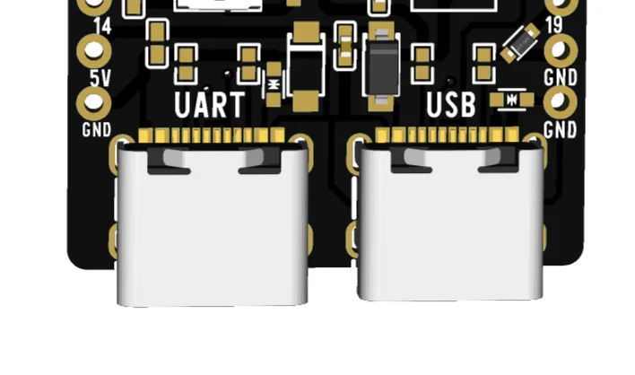
The right-hand socket, marked USB, is wired to the ESP32-S3's own USB hardware. The chip is the USB device: it enrols itself, on any operating system, with nothing to install. This is the one to start with.
The left-hand socket, marked UART, goes to a CH340K — a small chip whose entire job is to be a USB serial port on one side and a pair of UART pins on the other. It needs a driver on Windows, and on macOS versions that do not already ship one.
Which one to use
Start on the right. It needs no driver, it uploads faster, and it is the default every setting in this book assumes.
Move to the left when one of these is true:
- Your sketch crashes, sleeps deeply, or resets a lot. The left-hand port belongs to the CH340, not to your firmware, so it stays up through all three — and a crash log you can actually read is worth the driver install.
- You are watching the ROM boot messages. Those come out of UART0 before any setting of yours applies, so they leave by the left-hand socket regardless.
- The native port has stopped appearing and you want to keep working while you work out why.
The solder pad on the back
Turn the board over. Near the two USB-C sockets there is a small square solder pad — a jumper, left open.
Bridge it with a blob of solder and the 5 V rails of the two sockets become one. That is what makes this useful: a charger or a laptop on the left socket can then power a USB device plugged into the right one, which is what a USB-host project needs. Without the bridge the right-hand socket gives a device data lines and no power at all.
Two things change when you bridge it, and the second one is the one to think about before you reach for the iron.
Everything the device draws now goes through the left socket's series diode. That part was chosen to feed a board, not a peripheral. Keep the load modest — a keyboard, a small sensor, a memory stick that is not doing much — and check the board still boots reliably with the device attached, because a diode running near its limit drops more voltage and the brownout arrives as a mysterious reset rather than as an error.
For real current, that diode has to go too. Bridging it as well removes the ceiling — and removes the protection it was there to provide. From then on, a supply wired backwards reaches everything behind it instead of stopping at a part that costs cents. Do it on a board you power from one known-good source, and not on one that gets handed round a classroom.
Telling them apart when the board is upside down
The silkscreen on the back is mirrored, so USB reads on the left there.
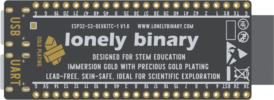
Two things are not mirrored and always work:
- The socket nearer the RESET button is the USB one.
- Plug in and look at the port list. The native port is a
usbmodemorACMname; the CH340 is awchusbserialorUSBname. That is worth learning once, because it is the same answer on every board you will ever own.
The code
Upload this and it prints which socket it is talking out of. Useful on a desk with both cables plugged in, and a two-second answer to "which of these is which".
/*  Lonely Binary ESP32-S3 N16R8 — which socket am I built for?
    Tools ▸ Board ESP32S3 Dev Module
           USB CDC On Boot  Enabled for USB, Disabled for UART  */

void setup() {
  Serial.begin(115200);
  delay(1500);              // the native port needs a moment to enrol

#if ARDUINO_USB_CDC_ON_BOOT
  Serial.println("Built for the USB socket, on the right.");
#else
  Serial.println("Built for the UART socket, on the left.");
#endif
}

void loop() {
  Serial.println("still here");
  delay(1000);
}
ARDUINO_USB_CDC_ON_BOOT is set by the Tools menu row of the same name, so this sketch reports the setting the sketch was built with — not the socket the cable is in. Those two agreeing is exactly what the next few articles are about.
When it does not work
That is the native port behaving correctly. It is created by the firmware running on the chip, so a reset, a deep sleep or a crash takes it away with it. Use the left-hand socket while you are debugging something that crashes, or hold BOOT and tap RESET to bring the ROM's port up.
Check Tools ▸ Port after unplugging one cable. Two ports means two devices, and the IDE will happily talk to the one you did not mean. Unplug the cable you are not using — with the pad bridged, the board still has power from the other socket.
Out of the box the two sockets share no 5 V rail, so a device plugged into the right one gets data lines and no power. That is what the solder pad on the back is for. It also has to be a project running USB host code — the socket does not become a hub on its own.
If a known-good cable powers the board on one socket and does nothing on the other, the series diode on the dead one has almost certainly failed open. That is a repair, and it has its own article at the end of this book.
The sockets are two of the four ways in. The other two are pins on the header, and one of them has nothing standing between your wiring and the regulator.
Powering the board →Edit this page — content/boards/esp32-s3/the-two-usb-c-ports.mdx
Questions about this product
See what other owners have asked, and read their solutions.
ESP32-S3 Gold Edition (N16R8)
Loading discussions…
Discuss this article
Ask about this page. The answer stays here, on the page it belongs to, for whoever hits the same wall next.