
Seat the board first
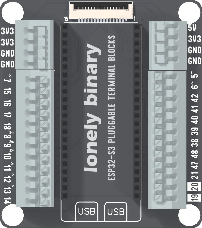
The ESP32-S3 fits this base two ways, and only one is right. Its two USB sockets go over the two boxes printed USB, with the antenna under the display plug. End for end, its 3.3 V output is wired to ground. Seat the board first, plug the cable in second.
Two boxes printed USB
Between the two black sockets, at the bottom of the base, are two outlines with USB printed in them. The ESP32-S3's two USB sockets go over those boxes. Its antenna end then sits at the top, under the display plug.
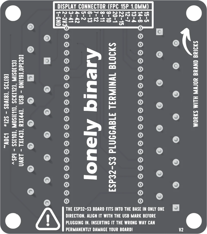
The back of the base says the same in words, bottom left beside a warning triangle: the board fits in only one direction, align it with the USB mark, and inserting it the wrong way can permanently damage your board.
That is the whole instruction. What follows is why it matters, because nothing on the base stops the other way.
It fits both ways
The two sockets are 22 positions long and 22.86 mm apart, identical, and so are the ESP32-S3's two rows of pins. Turn the board end for end and it seats as firmly as the right way. There is no key, no notch and no pin that is missing. The only thing between you and a damaged board is the printing.
What the pins meet
Turned end for end, the board's left row lands in the right-hand socket and runs the other way. Read off this base's net list:
- The board's two 3V3 pins land on the right socket's last two positions, which are GND. Its 3.3 V regulator output is wired to ground.
- The board's GND pins land on the left socket's first two positions, which are the 3V3 net, as well as on the base's own GND. The base's 3V3 terminals and the display plug's 3V3 contact are on that net.
- The board's 5V pin lands on the GPIO 43 socket, which is on no terminal.
- The board's GPIO 43 lands on the 5V terminal.
The ground inside the ESP32-S3 joins all its ground pins, so the base's 3V3 and GND terminals are now one wire, and that wire is the regulator's output.
What you will see
Most likely nothing comes up: no serial port, no upload. The regulator is driving a short, so it heats. The cost is a board you cannot tell apart from a dead one, and possibly a dead one.
A wire already in a 3V3 terminal is on the same net as every ground terminal. Whatever it feeds gets no voltage across it: a sensor wired between a 3V3 terminal and a GND terminal has its supply and ground joined, and one wired from a 3V3 terminal alone sits on the board's ground.
What to do
- Unplug the cable.
- Lift the ESP32-S3 out and turn it so its USB sockets are over the two boxes printed USB, the antenna under the display plug.
- Press it down evenly on both rows until it stops.
- Plug the cable in.
Seat the board first, the cable second, every time. The order is the whole protection.
When it does not work
Unplug the cable first, before anything else, then lift the board out and turn it round. Do not leave it powered while you decide. The silkscreen on the back of the base says the wrong way can permanently damage the board, so if it will not start after it has been turned round, the board may be the casualty and not the base.
Look at the antenna: the printed antenna end of the ESP32-S3 goes under the display plug, at the end with the ribbon socket. The two USB sockets are at the other end, over the two boxes marked USB. Both ends of the base look alike from the side, so check these two things and not the shape.
Check it has gone all the way down on both rows: a board sitting on the tips of its pins looks seated and does not connect. Press evenly along both edges. Then check the cable and the Port setting. The red power LED on the ESP32-S3 should be lit once a cable is in.
Take the cable out and pull the wire. Backwards, the 3V3 terminals sit on the same net as the ground terminals, so a sensor wired between them had its supply and its ground joined while the cable was in. Check it for heat before you use it again.
The base itself: two push-in blocks a side, and which GPIO is on which way.
The pluggable terminal base →Edit this page — content/books/esp32s3-base/pluggable-which-way-round.mdx
Questions about this product
See what other owners have asked, and read their solutions.
This page covers several products. Choose yours to see the right discussions.
Discuss this article
Ask about this page. The answer stays here, on the page it belongs to, for whoever hits the same wall next.