
The expansion base
Two 20-way 2.54 mm strips down each edge on the same nets, so a jumper goes in wherever one is free. Twenty-eight of the ESP32-S3's thirty-six GPIOs reach them; eight stop on the socket. There are no LEDs and no parts to fail, and the board still fits in end for end.
Four strips, two to an edge
This page assumes the ESP32-S3 is in, with its USB sockets over the two boxes printed USB. If you have not checked that, seat the board first.
The base is 48 by 72 mm and carries seven parts: two 22-way sockets for the ESP32-S3, four 20-way strips and a 15-way ribbon socket for a display. That is the whole bill of materials. Nothing on it is active, so nothing on it can fail or change what a pin does.
The strips run down both edges. Each edge has two, side by side, wired hole for hole to the same nets, so one jumper goes in the outer strip and another in the inner one on the same signal.
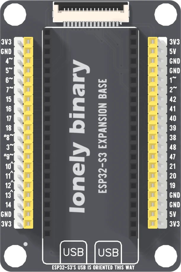
The outer strip of each edge is white pins and the inner strip is a yellow socket, so a jumper with a pin on one end and a socket on the other fits either way. The two strips of an edge are the same copper.
Twenty-eight of thirty-six
A strip is 20 holes. The ESP32-S3 has 44 header pins, of which 36 are GPIOs, and the strips carry 28 of them: sixteen on the left edge and twelve on the right. The rest of each strip is supply, laid out so that 3V3 and ground are never far from a signal.
The eight that do not come out are the ones the ESP32-S3 board is already using. 35, 36 and 37 are the octal PSRAM on the N16R8 module; driving one crashes the board. 43 and 44 are the serial port. 0, 45 and 46 are sampled at reset to choose how the chip boots. Reset itself stops on the socket too. None of that is a loss on this board: a wire on any of them would have been a wire on something that already has a job.
Two that do come out deserve a second look. GPIO 19 and 20 are the native USB pair, and GPIO 3 is another boot-time pin that floats by default. They are on the strips if you want them, with those facts attached.
One signal, two holes
Two strips on a net is for the jumper's sake, not the signal's. A sensor on one hole and a meter probe on the other both see the same pin, which is fine. Two things driving it is two outputs fighting; the copper does not know they arrived by different holes.
Power
3V3 is at both ends of every strip, with ground close by. It comes from the regulator on the ESP32-S3 board, so what you hang on it is spent from that regulator's budget, and the base adds no regulator of its own.
5V is on the right strips only, at the second and second-last holes. It is the ESP32-S3 board's own 5V pin, which sits on its left row, carried across the base by copper. On USB power it is the cable's 5 V less whatever the board drops on the way in, so do not treat it as a clean five. Ground is on both edges: two holes on each left strip, four on each right strip.
The display connector
The 15-way ribbon socket at the top is the one every Lonely Binary display takes, and it is wired the same way on all four ESP32-S3 bases: contact 1 ground, 2 3V3, 3 to 9 GPIO 41, 42, 2, 13, 12, 11 and 10, and 10 to 15 GPIO 1, 15, 7, 4, 6 and 5. The display plug says what each one does.
Every one of those thirteen GPIOs is also a strip hole, and nothing switches
the connection. Plug a display in and the display owns them; a wire on the same
hole is a second driver on the same line. The back of the board prints
contacts 10 and 11 as 20-1 and 22-15. A 15-way connector has no contact 20
or 22, so that is a typo in the legend and the wiring is the one above.
Which way round
Nothing on the base stops the ESP32-S3 going in end for end, and that way round its 3V3 pins land on the base's ground. Seat the board first is the page for it, with the net-list reading of what meets what.
What it does not have
No LEDs, so nothing shows what a pin is doing, and no pull-ups or pull-downs, so an input you leave alone floats. If you want to see the pins move, the PinPulse Shield is the same socket with a light on every GPIO. Four 4.8 mm mounting holes sit in the corners, and the tallest part stands 10.1 mm above the underside of the board. The silkscreen says the base works with LEGO Technic bricks, and the four mounting holes fit that: each is 4.8 mm across, the size of a Technic pin hole, and they are 40 by 64 mm apart, multiples of the 8 mm Technic pitch.
When it does not work
Eight GPIOs stop on the socket: 0, 35, 36, 37, 43, 44, 45 and 46. 35 to 37 are the module's PSRAM, 43 and 44 the serial link, 0, 45 and 46 are read at reset. Move the job to one of the 28 that come out; GPIO 4 to 7 and 15 to 18 on the left edge are free on the ESP32-S3 board.
Unplug the cable, then check the way round. The ESP32-S3's USB sockets go over the two boxes printed USB at the bottom of the base. End for end it fits just as firmly and puts its 3V3 pins on the base's ground. Turn it round before plugging anything in again.
There are two strips on each edge and they differ: the outer white one is pins and the inner yellow one is a socket. Use the strip your jumper's end suits; the two are the same copper.
That is the design. 5V is on the right-hand strips only, at the second and second-last holes. The left strips have 3V3 and ground at both ends and no 5V. Take 5V from the right edge, or from the ESP32-S3's own 5V pin.
The display connector is wired straight to thirteen strip holes, with nothing switching between them. A display that is plugged in owns those GPIOs, so a sensor on one of them is fighting the panel. Pick a GPIO that is not in the display table, or take the display off.
An input that nothing drives picks up whatever is nearby, and this base has no pull-ups or pull-downs to hold it. Set the pin as an output, or use INPUT_PULLUP, and it settles. It is the same effect as the flicker on the PinPulse Shield, with no LED to show it.
Where 3V3, 5V and ground are, and what stands behind them.
Power on the expansion base →Edit this page — content/books/esp32s3-base/the-expansion-base.mdx
Questions about this product
See what other owners have asked, and read their solutions.
This page covers several products. Choose yours to see the right discussions.
Discuss this article
Ask about this page. The answer stays here, on the page it belongs to, for whoever hits the same wall next.