What the shield does
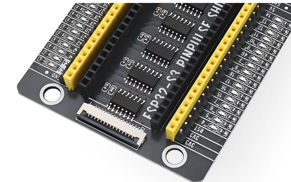
A socket for the ESP32-S3, every one of its pins brought out twice at the edge — once as a pin, once as a socket — an LED beside every GPIO, and a ribbon socket for a display. Here is which part is which.
A board for the board
The ESP32-S3 Gold Edition arrives with forty-four pins and nowhere convenient to put them. The shield is where they go: the board drops into two black 22-way sockets in the middle, and every one of its pins comes back out at the edges.
Six parts, one job each
Read from the outside in. The outer row on each edge is male pins, for the female end of a jumper wire. The yellow row beside it is female sockets, for the male end. Each socket is wired to the pin next to it, so the two rows are one set of signals offered twice.
Outside the pins is a column of LEDs, one beside every GPIO. Between the two black sockets, under where the board sits, are six inverter chips. They are what turns a pin's voltage into a lit LED without loading the pin, which is the subject of the next chapter.
At the top is a fifteen-way ribbon socket for a display, and at each corner a 4.7 mm mounting hole.
What the numbers mean
The number printed beside each row is the GPIO number — the one you type in
pinMode() and digitalWrite(). The shield uses the same order as the
ESP32-S3's own pins, so a GPIO sits at the same height on the shield as it does
on the board.
The rows with no LED are the ones that are not GPIOs: 3V3, 5V, RST and GND.
When it earns its place
When you want to see a pin rather than measure it. A sketch that toggles GPIO 5 shows a light on row 5 with no LED, no resistor and no wire. A serial port flickers while it talks. A pin you forgot to configure glows when you put a finger near it. Everything else — the pins, the sockets, the display port — is what any base does.
When it does not work
Each edge has two rows: male pins on the outside and yellow female sockets on the inside. They are the same 22 signals twice, wired together pin for pin, so count one row, not both.
The shield has no power of its own. Its LEDs and chips run from the ESP32-S3's 3.3 V output, so nothing lights until the board is seated and a USB cable is in.
74HC04D inverters — SN74HC04 in the board's bill of materials — six channels each, one channel per LED. They are what lets a GPIO light its LED without the LED's current coming out of the pin.
Only a 44-pin ESP32-S3 with the DevKitC-1 pin order: 22 pins a side, rows 22.86 mm apart, 3V3 at the antenna end of the left row. A board with a different order can seat and still put the wrong signal on the rows.
Edit this page — content/books/esp32s3-base/what-the-shield-does.mdx
Questions about this product
See what other owners have asked, and read their solutions.
ESP32-S3 N16R8 PinPulse Shield, 36 GPIO LEDs
Loading discussions…
Discuss this article
Ask about this page. The answer stays here, on the page it belongs to, for whoever hits the same wall next.