
The pluggable terminal base
Two 12-way push-in terminal blocks and two 4-way power blocks instead of pin rows: strip a wire, push it in, no solder and no screwdriver. Twenty-four GPIOs come out once each, and twelve of the S3's pins stay off the edge.
No jumper wires at all
With the board seated the right way round, this base takes the ESP32-S3 in two 22-way sockets and puts a wire terminal at each long edge instead of a row of pins. The wire goes in bare and a spring holds it: nothing to solder, crimp or tighten, and a press on the button above the way lets it go. The shop lists it as the Screwless Terminal base. It is the same board.
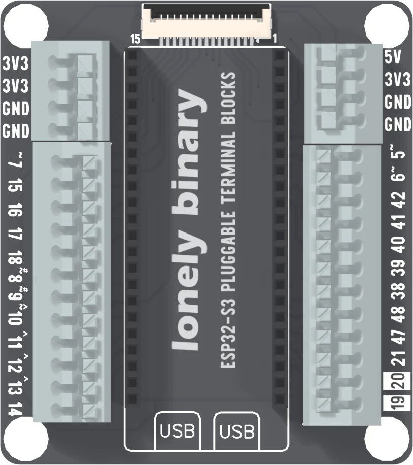
Each edge has a 4-way power block above a 12-way block, 3.5 mm between ways. The blocks are Kangnex WJ250B-3.5 spring-clamp terminals; a parts distributor lists them for 16 to 22 AWG wire and 8 A a way. That is the terminal's rating, not the board's: the power ways carry what the dev board's own pins supply. The board is 64 by 72 mm with four 4.8 mm mounting holes, and it stands 14.8 mm tall from its underside: the terminal blocks are the tallest parts on it.
What is on each way
Read it top to bottom, display connector at the top, as the silkscreen prints it.
Left power block: 3V3, 3V3, GND, GND. Left signal block: GPIO 7, 15, 16, 17, 18, 8, 9, 10, 11, 12, 13, 14. Right power block: 5V, 3V3, GND, GND. Right signal block: GPIO 5, 6, 42, 41, 40, 39, 38, 48, 47, 21, 20, 19.
Every GPIO way goes straight to the same pin of the ESP32-S3's socket, with nothing in between. The back prints the default buses beside them: I2C on 8 and 9, SPI on 10, 11, 12 and 13, native USB on 19 and 20.
What is not there
Twenty-four of the S3's 36 GPIOs have a way. GPIO 0, 1, 2, 3, 4, 35, 36, 37, 43, 44, 45 and 46 do not, and neither does RST. GPIO 1, 2 and 4 reach the display connector and nothing else. Most of the others are the pins the chip reads at reset, the serial port and the PSRAM, so a sketch rarely misses them. The pins at the edge page names what each one does.
GPIO 48 is on the right block, and on an S3 Gold it also drives the board's RGB LED, so a signal on that way can be seen on the LED.
Sharing with the display
The display connector at the top is the same 15-way plug on all four S3 bases, with the same GPIOs: contact 3 is GPIO 41, 4 is 42, 5 is 2, 6 is 13, 7 is 12, 8 is 11, 9 is 10, then 1, 15, 7, 4, 6 and 5 for contacts 10 to 15. The ribbon and a terminal way on those GPIOs are the same wire. A screen drives them, so put a sensor on a way the display does not use. The figure above picks them out.
Power
Both power blocks are the dev board's own pins carried out; there is no regulator on this base. The 3V3 ways are for a sensor taking its supply from the board, and the 5V way is the board's 5V pin. The next page says what each can give.
The way round
Seat the board before the cable goes in: its USB sockets go over the two boxes printed USB, and the antenna sits under the display plug. The first page of this chapter has what happens end for end.
The silkscreen says the base works with LEGO Technic bricks, and the four mounting holes fit that: each is 4.8 mm across, the size of a Technic pin hole, and they are 56 by 64 mm apart, multiples of the 8 mm Technic pitch.
When it does not work
A push-in way holds a bare, stripped conductor, and a stripped length that is too short leaves insulation under the spring while one that is too long leaves copper in the open. The part is a Kangnex WJ250B-3.5-12P, which a parts distributor lists for 16 to 22 AWG wire. To free a wire, press the button above its way and pull the wire out; do not force a wire in or out without pressing it. Tug the wire after it goes in; if it moves, it never seated.
Ignore the numbering in the design files and read the silkscreen. Every block is printed top to bottom with the display connector at the top, and the lists in this article follow it. The right power block starts at 5V, the left at 3V3.
Twenty-four GPIOs fit on the blocks and these were left off, along with 1, 2, 4, 35, 36 and 37. Several of them are pins the chip reads while it boots or that carry the serial port and the PSRAM, which are the ones to avoid anyway. GPIO 1, 2 and 4 are on the display connector only. If a sketch needs one of the others, the expansion base brings out more.
Those are the two data lines of the S3's own USB port, the last two ways on the right block. Anything wired to them loads the USB bus. Choose another way, or unplug the sensor while uploading.
Ways 7, 15, 10, 11, 12, 13 on the left and 5, 6, 42, 41 on the right are also contacts on the display connector. A plugged-in screen drives those lines, so a sensor wired to one is sharing it with the screen. Move the sensor to a way the display leaves alone.
The 5V way is the dev board's 5V pin, which reads a little under 5 V when USB is plugged in. It is for a 5 V load, not a regulator output; see the power article for how it behaves with no cable.
Which ways carry 3V3, 5V and ground, and what stands behind them.
Power on the pluggable terminal base →Edit this page — content/books/esp32s3-base/the-pluggable-terminal-base.mdx
Questions about this product
See what other owners have asked, and read their solutions.
This page covers several products. Choose yours to see the right discussions.
Discuss this article
Ask about this page. The answer stays here, on the page it belongs to, for whoever hits the same wall next.