
Seat the board first
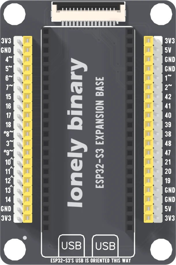
The ESP32-S3 goes into this base with its two USB sockets over the two boxes printed USB and its antenna under the display connector. It seats just as firmly end for end, and that way round its 3.3 volt output is wired to its own ground. Seat the board first, plug the cable in second.
Seat the board first, plug the cable in second
The ESP32-S3's two USB sockets go over the two boxes printed USB at the bottom of the base. Its antenna end then sits under the display connector at the top. That is the whole instruction. Do it before the cable goes in, every time.
The back of the base repeats it in a warning box: the board fits in one direction only, align it with the USB mark before plugging in, and the wrong way can permanently damage it.
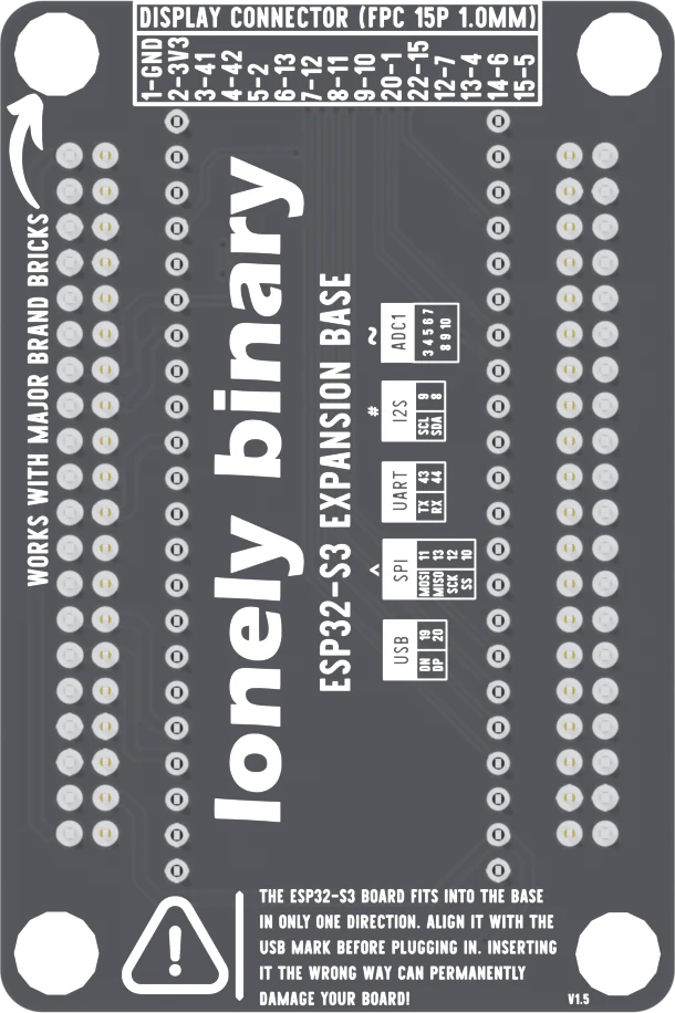
Nothing stops the wrong way
Both sockets are 22 ways long and 22.86 mm apart, the same as the ESP32-S3's two rows of pins, and there is no key, no notch and no shroud. Turned end for end the board drops in as firmly as the right way. The only things that say which is right are the silkscreen and you.
What it does end for end
Turned round, the board's left row goes into the right socket, running the other way. Read from this base's net list:
- The board's two 3V3 pins land on the base's two ground sockets. Its regulator output is wired straight to ground.
- Two of its four ground pins land on the base's 3V3 sockets, so the 3V3 holes on the strips are now the board's ground.
- Its 5V pin lands on the GPIO 43 socket. Nothing else on the base uses that net, so on its own this does nothing. The board's GPIO 43 pin lands on the base's 5V net instead, which is every 5V hole on the right strips.
The third is why jumpers come off before the board is reseated: whatever was wired to a 5V hole was wired to a GPIO.
What you will see
Nothing lights. Not the red power LED on the ESP32-S3, because the rail it sits on is shorted. The regulator gets warm, then hot. Your computer may complain about the USB port.
The regulator limits its own current and shuts down when it overheats, so a few seconds backwards is often survivable. Often is not always. Cable out first, then the board; turn it round, seat it, and only then plug in.
When it does not work
Unplug the cable before anything else. Then look at the USB sockets: if they are at the display connector end, the board is in end for end. Lift it out straight, turn it round so the sockets are over the boxes printed USB, and try again.
Often not. The regulator on the ESP32-S3 limits its own current and shuts down when it overheats, which is what a short makes it do, so a few seconds backwards is frequently survivable. Turn it round and try it. It is not guaranteed, so do not leave it plugged in to find out.
End for end, the board's GPIO 43 pin lands on the base's 5V net, so anything wired to a 5V hole was wired to that pin. Check a sensor on those holes before you trust it again, and take the jumpers off before you reseat the board.
A pin is folded under the board or missed its socket. Lift it out straight, check that all 44 pins are straight, and press down evenly at both ends. A half-seated pin works one minute and not the next.
Four strips of pins, 28 GPIOs on each edge twice, and the display connector.
The expansion base →Edit this page — content/books/esp32s3-base/expansion-which-way-round.mdx
Questions about this product
See what other owners have asked, and read their solutions.
This page covers several products. Choose yours to see the right discussions.
Discuss this article
Ask about this page. The answer stays here, on the page it belongs to, for whoever hits the same wall next.