Which way round
The ESP32-S3 drops into the shield just as easily end for end as the right way round, and the wrong way wires its 3.3 volt output to its own ground. The two boxes printed USB are the whole check.
Two boxes printed USB
At the bottom of the shield, between the black sockets, are two small outlines with USB printed in them. The ESP32-S3's two USB sockets go over those boxes. Its antenna then sits at the other end, under the display port.
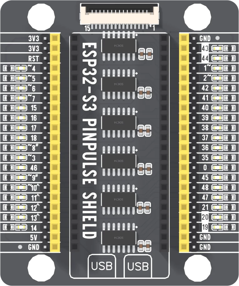
That is the whole instruction. What is worth a page is why it matters, because nothing on the board stops the other way.
It fits both ways
Both black sockets are 22 positions long and 22.86 mm apart, and the board's two rows of pins are too. Turn the board end for end and it seats just as firmly.
Turned round, the board's left row goes into the shield's right socket and runs the other way. So the board's two 3V3 pins land on the shield's bottom-right GND rows — and that ground row is also where two of the board's real ground pins have landed. The regulator's output is now wired straight to ground.
At the same time the board's 5V pin lands on the shield's GPIO 43 row, which goes into one of the inverter chips, whose own supply is now at zero.
What you will notice
Nothing lights. Not the shield's LEDs and not the red power LED on the ESP32-S3 itself, because the 3.3 volt rail it sits on is shorted. The regulator gets hot. Your computer may complain about the USB port.
So: seat the board first, then plug in the cable. If nothing lights, the cable comes out before anything else happens, and then you look at which end the USB sockets are.
The regulator on the ESP32-S3 has its own current limit and shuts itself down when it overheats, so a few seconds backwards is often survivable. It is still the one mistake on this board that can end a session.
When it does not work
Unplug the cable first, then look at the USB sockets. If they are at the display-port end rather than over the boxes printed USB, the board is in backwards and its 3.3 V output is shorted to ground. Take it out, turn it round, and try again before plugging anything else in.
Often not. The regulator on the ESP32-S3 limits its own current and shuts down when it gets too hot, which is what a short makes it do. Turn the board round and try it. If it now uploads and the LEDs work, carry on; if an LED column stays dark, the inverter chip for that group may be damaged.
A pin is folded under the board or missing its socket. Lift it out straight, check that all 44 pins are straight, and press down evenly with a thumb at each end. A half-seated pin works one moment and not the next.
The board is one socket position too far up or down, with a pair of pins hanging off the end. Both black sockets are exactly 22 long, so the board's ends should line up with the socket ends.
Thirty-six lights on your signals, and why they cost those signals nothing.
How a pin lights its LED →Edit this page — content/books/esp32s3-base/which-way-round.mdx
Questions about this product
See what other owners have asked, and read their solutions.
ESP32-S3 N16R8 PinPulse Shield, 36 GPIO LEDs
Loading discussions…
Discuss this article
Ask about this page. The answer stays here, on the page it belongs to, for whoever hits the same wall next.