
The screw terminal base
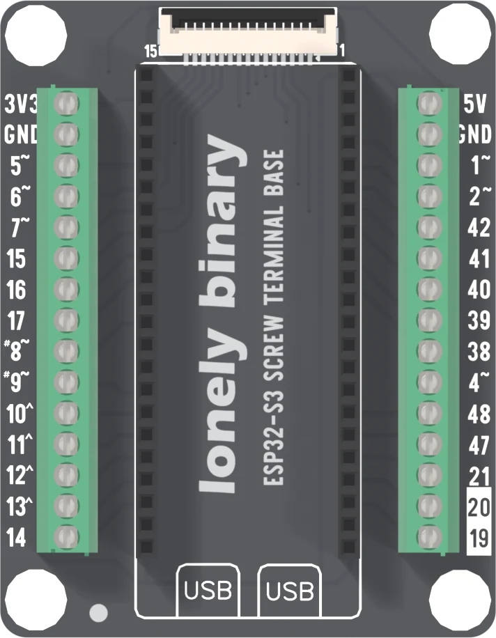
Two 15-way screw blocks bring out 26 GPIOs, each once. Two things are not where the dev board's own rows would put them: GPIO 4 comes out on the right block, and 3V3 and 5V are on different blocks.
Wiring that stays put
An ESP32-S3 Gold Edition plugs into the two sockets down the middle. A block of fifteen screw terminals runs down each edge at a 3.5 mm pitch, one way for each pin that comes out. This is the base for something that will be carried, driven somewhere or left alone for a year. There are no pins to solder, and nothing on the board but the sockets, the two blocks and the display connector: no regulator, no LEDs, nothing between a screw and the dev board's pin. If the dev board is not seated yet, seat it first.
The wire goes into the terminal and the screw clamps it. A screw that has closed on insulation feels tight and tests dead, so back it out until you can see the clamp open, put bare copper under it, and tighten until the wire will not pull out by hand.
Read the label, not the row
The dev board's pins are in two rows, and it is natural to think the left row comes out on the left block. Nearly all of it does. Two pins do not.
GPIO 4 is on the dev board's left row and on the right block, tenth from the top between 38 and 48. The net list ties the two together. So does 5V: a left-row pin that comes out on the right. Wire a sensor by counting down the dev board's rows and GPIO 4 goes on the wrong side, and a sketch that reads it finds a pin with nothing on it.
The silkscreen is right and the row is not a guide. Read the number printed beside the screw, or click the way in the 3D view.
3V3 on one side, 5V on the other
3V3 is on the left block, top way. 5V is on the right block, top way. There is one of each. Both are the dev board's own pins passed through, and there is nothing on the base to regulate or protect them: a short from either way is a short on the dev board's supply.
The cost is wiring. A module with a signal on the right block that wants 3.3 V
needs a wire from the left block, across the board. If it can take 5 V it takes
it from its own side. Each block has one GND way as well, so each side has
its own ground, and they are the same net.
What is left out
The base brings out 26 of the dev board's 36 header GPIOs. GPIO 0, 3, 18, 35, 36, 37, 43, 44, 45 and 46 stop at the socket, and so does RST. That leaves out the serial pair, the PSRAM lines of an N16R8 module and all four strapping pins, which is a list of pins a beginner is better off not wiring in any case. The cost is that a project that needs one of them cannot use this base.
The last two ways on the right block, 20 and 19, are printed on a white box. They are the dev board's native USB pair, so a wire there shares a line with the computer. See the pins at the edge for what the dev board already uses.
The display connector shares the ways
The 15-way ribbon socket at the top is the same on every ESP32-S3 base. Its contacts 3 to 15 are GPIO 41, 42, 2, 13, 12, 11, 10, 1, 15, 7, 4, 6 and 5, and every one of them is also a terminal way. Nothing switches them: a wire on GPIO 12's way is on the display's clock line too. Which contact is which GPIO is on the display port.
Seat the dev board the right way round
The two sockets are identical, 22.86 mm apart, so the dev board also fits end for end. The antenna end goes toward the display connector and the two USB sockets over the two boxes printed USB. The wrong way round puts the dev board's 3V3 pins on the base's ground; the page before this one shows what happens and what to do.
Mounting
The silkscreen says the base works with LEGO Technic bricks, and the four mounting holes fit that: each is 4.8 mm across, the size of a Technic pin hole, and they are 48 by 64 mm apart, multiples of the 8 mm Technic pitch.
When it does not work
GPIO 4 is not on the left block, although it sits on the dev board's left row. It is on the right block, the tenth way down from the display end, between 38 and 48. Move the wire there, or read the number printed beside the screw and not the row you counted.
3V3 is on the left block only, and 5V on the right block only, one way each. A module on the right block that wants 3.3 V needs a wire from the left block's top way across the board, or power it from 5V if it takes that.
Ten GPIOs stop at the socket: 0, 3, 18, 35, 36, 37, 43, 44, 45 and 46, and RST as well. Nothing on this base reaches them. If a project needs one of them, use the PinPulse shield, which brings out every GPIO the dev board has.
The clamp has closed on insulation, or beside the copper. Back the screw out until you can see the clamp open, put bare copper under it with no insulation inside the clamp, tighten until the wire will not move, and tug it.
The display connector's lines are the same nets as terminal ways: GPIO 41, 42, 2, 13, 12, 11, 10, 1, 15, 7, 4, 6 and 5. With a display fitted, a wire on one of those ways is on the display's line too. Use a way the display leaves unused.
Check which way round it went. The two sockets are identical, so the board also fits end for end, and that way its 3V3 pins land on the base's ground. Unplug the cable first. The two USB sockets go over the two boxes printed USB.
Where 3V3 and 5V come from, and what the radio does to them.
Power on the screw terminal base →Edit this page — content/books/esp32s3-base/the-screw-terminal-base.mdx
Questions about this product
See what other owners have asked, and read their solutions.
This page covers several products. Choose yours to see the right discussions.
Discuss this article
Ask about this page. The answer stays here, on the page it belongs to, for whoever hits the same wall next.