The display port
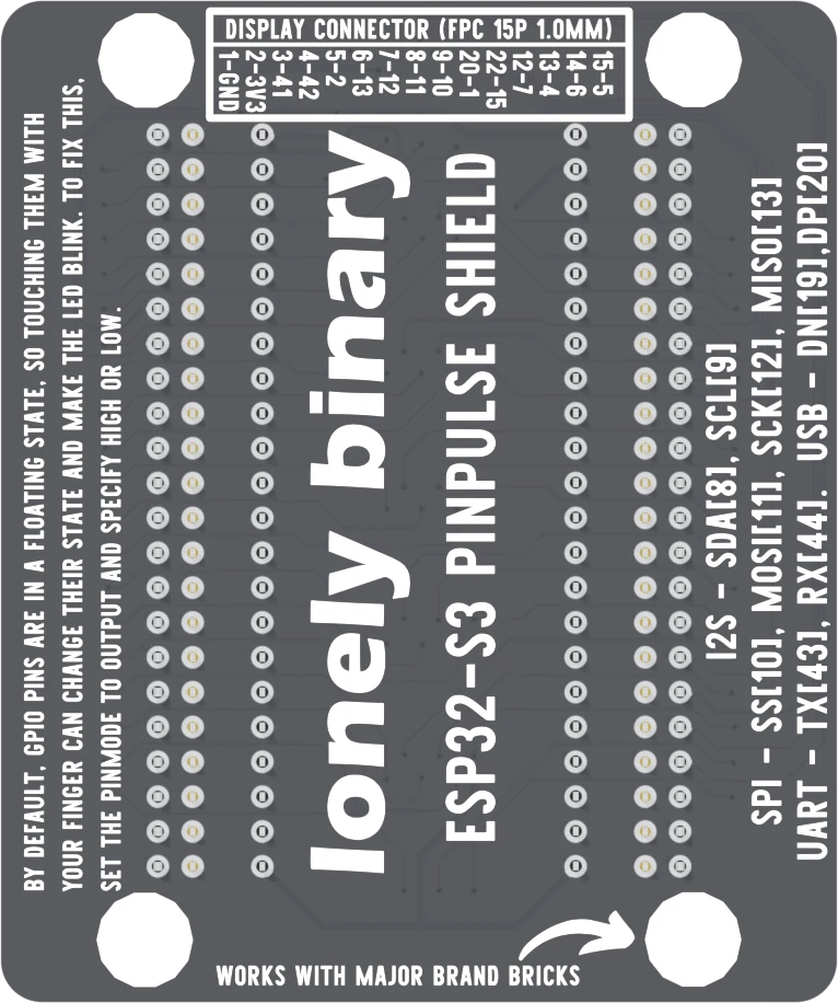
A fifteen-way ribbon socket at the top of the shield carries ground, 3.3 volts and thirteen GPIOs to a display. The table on the back lists every contact — and misnumbers two of them.
Fifteen contacts at one millimetre
At the top of the shield, above the six chips, is a white socket fifteen contacts wide at a 1.0 mm pitch. A display with a matching flat ribbon plugs straight in, which replaces a bundle of loose jumpers with one cable that can only go in straight.
Contact by contact
Contact 1 is ground and contact 2 is 3.3 volts. Contacts 3 to 15 are thirteen GPIOs, in this order: 41, 42, 2, 13, 12, 11, 10, 1, 15, 7, 4, 6 and 5. The silkscreen beside the socket prints a 1 at the right-hand end and a 15 at the left, as the board sits with the socket at the top.
Every one of those thirteen GPIOs is also on the edge rows, with its own LED. The ribbon adds no pins; it is a second way onto thirteen you already have.
The two rows to ignore
The table on the back prints 20-1 and 22-15 where it should print 10-1 and 11-15. There is no contact 20 or 22 on a fifteen-way socket, and the board's wiring confirms it: contact 10 is GPIO 1, contact 11 is GPIO 15. The table's order is right. Only those two numbers are wrong.
Which pin does what
Which line is chip select, which is data/command and which is backlight is decided by the display on the other end of the ribbon, not by the shield. The board's design files do name three of the lines — CS on GPIO 10, DC on GPIO 2 and BL on GPIO 41 — which is a strong hint, but the display's own pin table is the one to follow. Use the GPIO numbers above in your sketch.
Four of the thirteen — GPIO 10, 11, 12 and 13 — are the ESP32-S3's default SPI pins, which is what most small displays speak. The others are free for the display's control lines.
When it does not work
Check the ribbon first: fully inserted, square to the socket, latch closed, and the contacts facing the way the display's instructions say. A ribbon upside down connects nothing and damages nothing. Then check your sketch's pin numbers against the contact list on this page, not against rows 10 and 11 of the table on the back.
A typing slip in the legend. A fifteen-way socket has no contact 20 or 22; those rows are contacts 10 and 11, and they are wired to GPIO 1 and GPIO 15, in the order the table prints them. Every other row of the table is correct.
Every GPIO on the ribbon also has an LED at the edge, so the lines the display uses flicker while it draws. That is the display bus working, and a quick check that the sketch is really sending something.
Only the ones the display leaves unused. The ribbon and the edge rows are the same wires, so anything you connect at the edge is also on the display's line. Unplug the ribbon to use those pins for something else.
A first sketch that walks a light down every pin it is safe to drive.
Chase the LEDs →Edit this page — content/books/esp32s3-base/the-display-port.mdx
Questions about this product
See what other owners have asked, and read their solutions.
ESP32-S3 N16R8 PinPulse Shield, 36 GPIO LEDs
Loading discussions…
Discuss this article
Ask about this page. The answer stays here, on the page it belongs to, for whoever hits the same wall next.