Specifications
| Soft keypad 5-pack | 5 flexible membrane keypads, 69 × 76 mm with an adhesive back, and 5 adapters with pins, in a storage box |
|---|---|
| Heavy-duty 2-pack | 2 rigid keypads with raised keys and 8 pins soldered on, and 2 adapters with a socket |
| TinkerBlock TK85 | The adapter on a TinkerBlock board with mounting holes, in the 46-piece kit |
| Adapter chip | PCF8574 I²C I/O expander: 8 port pins, P0–P7, one per keypad wire |
| Wires to your board | 4 — GND, VCC, and the 2 signal wires SDA and SCL |
| Supply voltage | 2.5–6 V for the chip. Use your board's own 3.3 V or 5 V: the I²C pull-ups go to VCC |
| I2C address | 0x20 as shipped; 0x20–0x27 with the three pads on the back |
| I2C clock | 100 kHz at most, per the PCF8574 datasheet |
| Pull-ups | 10 kΩ on SDA and on SCL, removable by cutting the I2C PULL UP pad |
| Keys | 16 in a 4 × 4 grid, read one at a time |
What it does
A 4×4 matrix keypad is sixteen switches wired as four row wires and four column wires: pressing a key joins one row to one column. That is eight wires, and wired straight to a board it is eight GPIO pins — nearly half an Arduino Uno.
The adapter moves those eight wires onto a PCF8574, a chip with eight pins of its own that is controlled over I²C. What is left on your board is the I²C bus: SDA and SCL, plus power and ground. Screens, sensors and clocks share the same two wires, each at its own address. The adapter ships at 0x20.
The I2CKeyPad library by Rob Tillaart reads a key with two writes and two reads, and returns a number from 0 to 15. A keymap string turns that into the character printed on the key.
The boxes
Three products carry the same adapter circuit. What differs is the keypad.
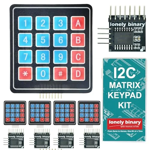
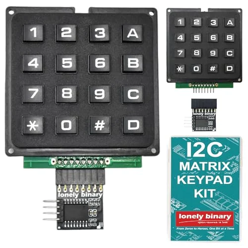
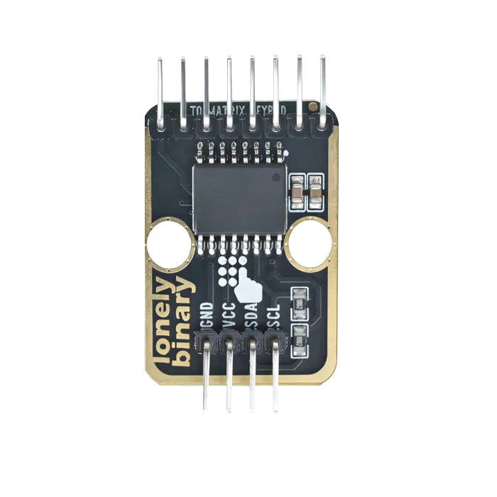
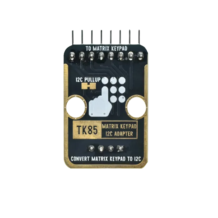
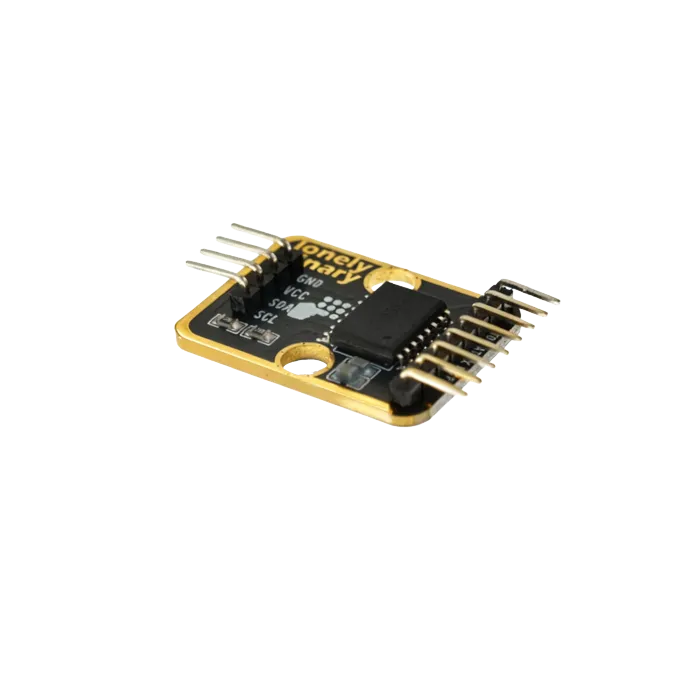
The TinkerBlock TK85, above, is the adapter on a TinkerBlock board with mounting holes for the base plate, and comes in the 46-piece kit.
Which keymap
| Keypad | Comes in | Keymap |
|---|---|---|
| Soft membrane | the 5-pack, and the TK85 as photographed | DCBA#9630852*741NF |
| Heavy-duty | the 2-pack | D#0*C987B654A321NF |
The soft keypad brings its rows out first and the heavy-duty keypad its columns, so the same key lands on a different number. A keypad from anywhere else: run the keymap finder.
Wiring, in four lines
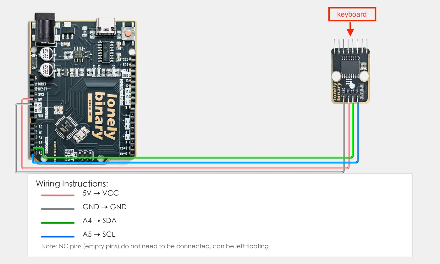
- GND to the board's GND.
- VCC to the board's own logic voltage: 5V on an Uno, 3V3 on an ESP32.
- SDA to the board's SDA: A4 on an Uno, GPIO 21 on an ESP32, GPIO 8 on an ESP32-S3.
- SCL to the board's SCL: A5, GPIO 22, GPIO 9.
VCC matters because the adapter's own 10 kΩ pull-ups tie SDA and SCL to it. Fed from 5 V next to an ESP32, the bus idles at 5 V against 3.3 V pins.
Two on one bus
Every adapter ships at 0x20. Two on the same board need different addresses, set by bridging one of the three pads on the back with solder. The pads printed A0 and A2 are wired the other way round: bridging the one marked A0 gives 0x24, and the one marked A2 gives 0x21. Scan after soldering and use what it prints.
Each adapter also brings a pair of 10 kΩ pull-ups. With more than a handful on one bus, cut the I2C PULL UP pad on all but one. More than one keypad works through both.
Example
Install I2CKeyPad from the Arduino Library Manager. The MicroPython version does the same two reads by hand and needs no library.
#include <Wire.h>
#include "I2CKeyPad.h"

// 16 keys, then N (no key) and F (fail). Pick the one for your keypad.
char keymap[19] = "DCBA#9630852*741NF";      // soft keypad
// char keymap[19] = "D#0*C987B654A321NF";   // heavy-duty keypad

I2CKeyPad keyPad(0x20);
char last = 'N';

void setup() {
  Serial.begin(115200);
  Wire.begin();
  Wire.setClock(100000);   // the PCF8574 is rated for 100 kHz
  if (!keyPad.begin()) {
    Serial.println("No keypad at 0x20");
    while (true) delay(1000);
  }
  keyPad.loadKeyMap(keymap);
}

void loop() {
  char c = keyPad.getChar();
  if (c != last) {
    if (c != 'N' && c != 'F') Serial.println(c);
    last = c;
  }
  delay(20);
}from machine import Pin, I2C
import time
ADDRESS = 0x20
KEYMAP = "DCBA#9630852*741" # soft keypad
# KEYMAP = "D#0*C987B654A321" # heavy-duty keypad
# Raspberry Pi Pico: I2C0 on GP0 (SDA) and GP1 (SCL). Change the pins for your board.
i2c = I2C(0, sda=Pin(0), scl=Pin(1), freq=100_000)
ONE = {0xE: 0, 0xD: 1, 0xB: 2, 0x7: 3} # exactly one line low
def read(mask):
i2c.writeto(ADDRESS, bytes([mask]))
return i2c.readfrom(ADDRESS, 1)[0]
def get_key():
upper = (read(0xF0) >> 4) & 0x0F # which of P4-P7 the key pulled low
lower = read(0x0F) & 0x0F # which of P0-P3 the key pulled low
if upper == 0x0F or lower == 0x0F:
return None # no key
if upper not in ONE or lower not in ONE:
return "F" # two keys at once
return KEYMAP[ONE[upper] + 4 * ONE[lower]]
last = None
while True:
key = get_key()
if key != last and key not in (None, "F"):
print(key)
last = key
time.sleep_ms(20)Where to start
The handbook below is eleven short articles with a working figure in each. If you only read one, read one adapter, two keymaps. If you want keys on the serial monitor now, the first keypress is the whole build.
When it doesn’t work
- Nothing responds.
- Scan the bus. The adapter answers at 0x20 as shipped, or 0x20–0x27 if a pad on the back is bridged; a PCF8574A chip would answer at 0x38–0x3F. If nothing answers anywhere, the fault is GND, VCC, SDA or SCL — on an Uno those last two are A4 and A5.
- Every key prints a different key.
- The sketch has the other keypad's keymap. The soft keypad needs "DCBA#9630852*741NF" and the heavy-duty keypad "D#0*C987B654A321NF". With the wrong one, 2 prints 4 and A prints *, while 1, 5, 9 and D look fine.
- Two keys at once prints F.
- That is the I2CKeyPad library refusing to guess. A second key pulls a second line low, and it returns FAIL rather than report a key that may not have been pressed. The keypad reads one key at a time.
- I bridged the A0 pad and the adapter is at 0x24, not 0x21.
- The design files wire the pad printed A0 to the chip's A2 pin, and the pad printed A2 to A0; only A1 is as labelled. The address is still different from 0x20, which is what matters. Always scan after soldering and use the address it prints.
- Can I power the adapter from 5 V on an ESP32?
- No. The adapter's pull-ups tie SDA and SCL to its VCC, so from 5 V both lines sit at 5 V against 3.3 V pins. The chip runs from 2.5 V, so feed it 3V3.
- An old sketch sets the I²C clock to 400 kHz.
- Set it to 100 kHz. That is the PCF8574's rated maximum, and a key still reads in well under a millisecond.