Specifications
| Type | Mechanical key switch with integrated LED |
|---|---|
| Switch | Momentary, normally open |
| LED | Independent, with series resistor |
| Supply voltage | 3.3 V or 5 V |
| Pins | Separate lines for the switch and the LED |
What it is
A proper mechanical switch — the kind in a keyboard — with an LED under the cap. The two are electrically independent: pressing the key does not light the LED unless your code says so.
That independence is what makes it more than a button. The light can mean whatever the state actually is rather than what the finger just did: armed, recording, connected. A key that lights when pressed tells you nothing you did not already know.
Mechanically it is a real switch with a defined actuation point and a life measured in millions of presses, which is a different experience from a tactile dome. It also bounces, like everything else with contacts.
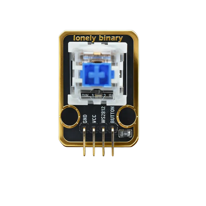
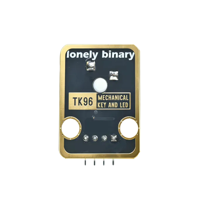
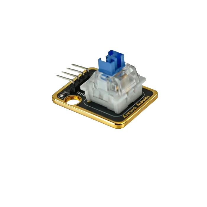
Pinout
- GND (negative): Like the negative terminal (-) of a battery, connect to the control board's GND
- VCC (positive): Like the positive terminal (+) of a battery, connect to the control board's 5V (Note: WS2812 requires 5V)
- WS2812 (data line): WS2812 LED data line, connect to the control board's digital pin (e.g. Arduino D6 or Pico GPIO 0)
- BUTTON (key): Key detection output pin, connect to the control board's digital pin (e.g. Arduino D2 or Pico GPIO 1)
- Outputs LOW (LOW/0) when key pressed
- Outputs HIGH (HIGH/1) when key released
Wiring
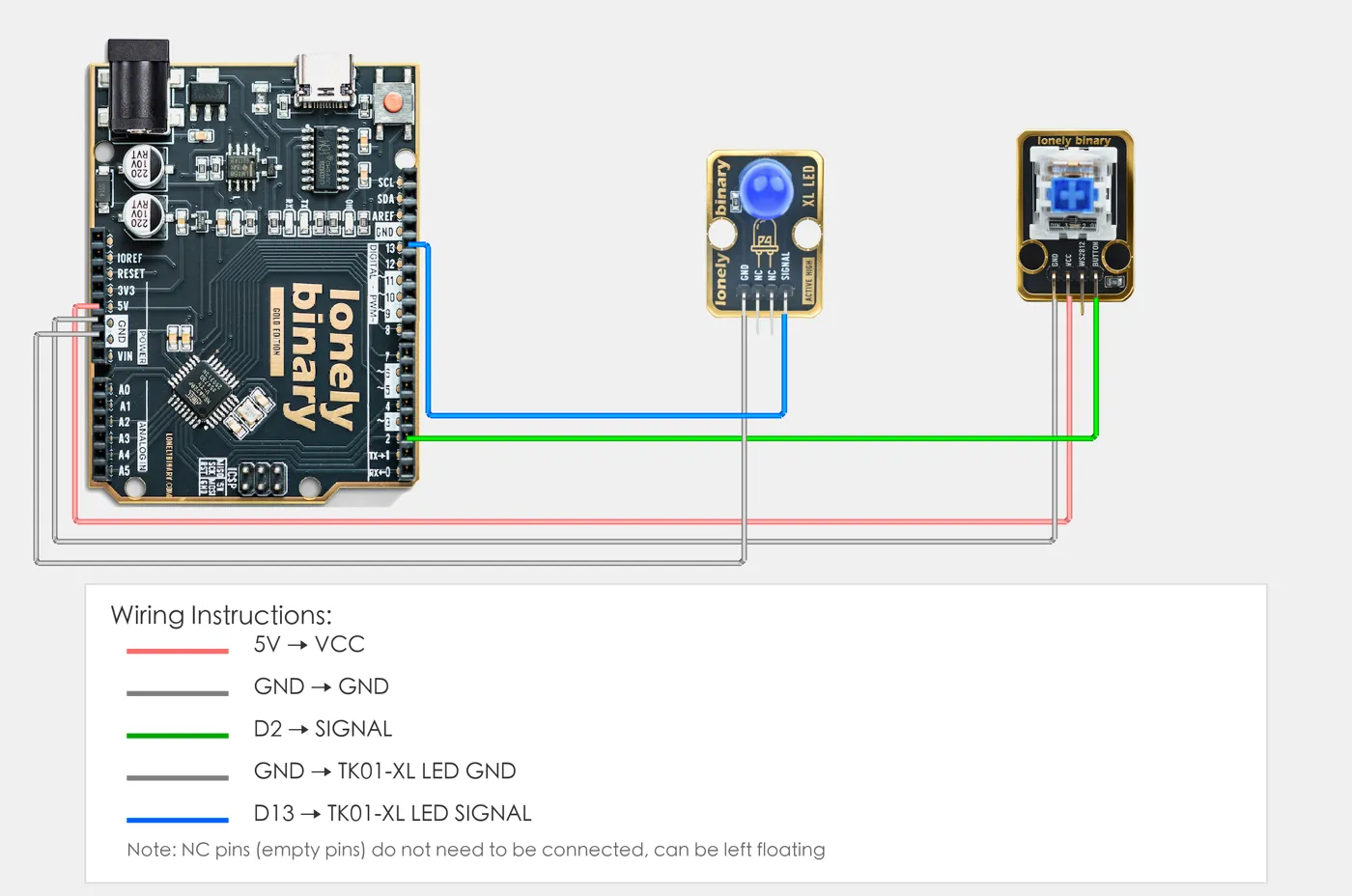
- GND → Control board GND
- VCC → Control board 5V
- WS2812 → Control board digital pin (to control LED)
- BUTTON → Control board digital pin (to detect key)
Example
// Pin number: change this to match your wiring
#define BUTTON_PIN 2   // Arduino digital pin connected to BUTTON (e.g. D2)
#define LED_PIN 13     // LED pin (Arduino built-in LED on pin 13, or external LED)

void setup() {
  // Initialize pin modes
  pinMode(BUTTON_PIN, INPUT_PULLUP);  // Set button pin as input mode, enable internal pull-up resistor
  pinMode(LED_PIN, OUTPUT);           // Set LED pin as output mode (to control LED on/off)

  // Start serial for debugging (9600 baud)
  Serial.begin(9600);

  Serial.println("Mechanical key program started");
  Serial.println("LED on when key pressed, LED off when key released");
}

void loop() {
  // Read button state
  int buttonState = digitalRead(BUTTON_PIN);  // Read button pin level: LOW(0)=pressed, HIGH(1)=released

  // Control LED based on button state
  if (buttonState == LOW) {
    // Key pressed: LED on
    digitalWrite(LED_PIN, HIGH);
    Serial.println("Key pressed - LED on");
  } else {
    // Key released: LED off
    digitalWrite(LED_PIN, LOW);
    Serial.println("Key released - LED off");
  }

  delay(100);  // Brief delay to avoid reading too fast
}# Import required modules
from machine import Pin # GPIO control
import time # For delay (time.sleep)
# Pin number: change this to match your wiring
BUTTON_PIN = 0 # GPIO connected to BUTTON (e.g. GPIO 0)
LED_PIN = 1 # LED pin (GPIO 1, or external LED, Pico built-in LED is GPIO 25)
# Create pin objects
button = Pin(BUTTON_PIN, Pin.IN, Pin.PULL_UP) # Set button pin as input mode, enable pull-up resistor
led = Pin(LED_PIN, Pin.OUT) # Set LED pin as output mode (to control LED on/off)
print("Mechanical key program started")
print("LED on when key pressed, LED off when key released")
# Main loop: runs forever
while True:
# Read button state
buttonState = button.value() # Read button pin level: 0=pressed (LOW), 1=released (HIGH)
# Control LED based on button state
if buttonState == 0:
# Key pressed: turn LED on and print message
led.on() # Output HIGH, LED on
print("Key pressed - LED on")
else:
# Key released: turn LED off
led.off() # Output LOW, LED off
print("Key released - LED off")
# Delay 100 milliseconds to avoid reading too fast
time.sleep_ms(100)When it doesn’t work
- The LED does not light when I press the key.
- It is not supposed to — they are separate circuits. Set the LED pin in code when the key is read.
- One press counts as several.
- Contact bounce, same as any mechanical switch. Debounce for 20–30 ms.
- The LED is dim.
- It has a series resistor sized for 5 V. From 3.3 V it will be noticeably dimmer, which is normal.