Specifications
| Type | Capacitive touch pad, one key |
|---|---|
| Chip | Tontek TTP233H-BA6 in SOT-23-6, marked 233HB. The silkscreen and the box both say TP223; the part the board's BOM specifies is the TTP233H-BA6, and every number here comes from its datasheet |
| Output | One digital pin. CMOS push-pull, HIGH while the pad is touched |
| Output mode | Active-high and momentary, tied that way in copper. There is no jumper and no toggle mode on this board |
| Supply voltage | 2.4–5.5 V |
| Response time | 46 ms while awake, 160 ms once idle, both measured at 3 V |
| Supply current | 1.5 µA idle and 4 µA awake, typical at 3 V with nothing on the output |
| Sensitivity capacitor | 22 pF fitted. The chip takes 1–50 pF, and a smaller value is more sensitive |
| Settling time | About 0.5 s after power-up, during which the pad must be left alone |
| Wires to your board | 3 — GND, VCC and SIGNAL. The fourth pin, NC, goes nowhere |
| Fitted on the board | A red LED and a 1 kΩ resistor across SIGNAL, and a 100 nF supply capacitor |
| The 12-pack | 12 boards in a hinged storage case |
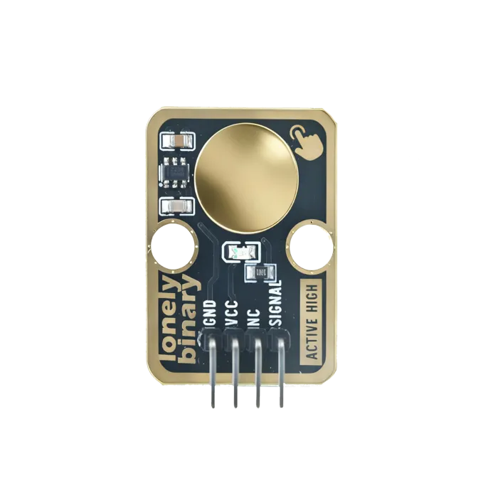
| Board | 22.4 × 32.4 mm, two mounting holes, a 4-pin 2.54 mm header footprint printed GND, VCC, NC, SIGNAL |
What it does
The chip measures the capacitance of the copper disc on the front of the board.
Your finger, brought near it, is a few picofarads of change, and the chip
reports that change on one pin. As far as your program is concerned this is a
button: digitalRead returns HIGH while the pad is touched and LOW when it is
not.
What it buys you over a button is that nothing moves. There is no contact to wear out, no bounce to debounce, and because capacitance passes through an insulator the pad can sit behind a sealed panel with no hole cut in it. That is the whole reason to choose one.
The boxes
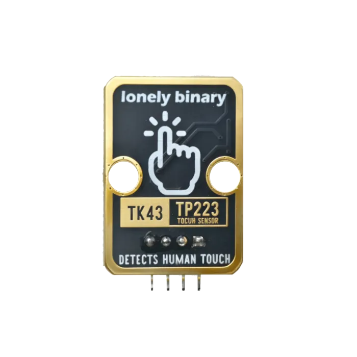
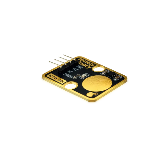
Two, holding the same board. The TinkerBlock TK43 is one of the forty-six parts in the sensor kit, with the mounting holes that fit the base plate. The 12-pack is twelve of it in a hinged case, for when one project wants six touch points and you would rather not buy six kits.
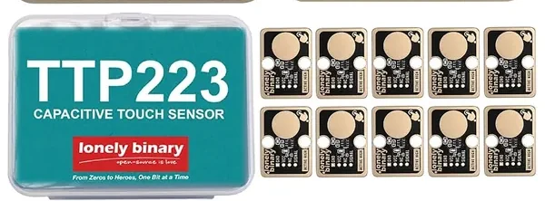
One thing to check before you order, because our own pictures differ on it: the board renders above have a 4-pin header soldered in, and the 12-pack's product photo shows the holes bare. Go by the photograph on the listing you are buying from, and if you are breadboarding, have a strip of 2.54 mm header pins to hand.
There is no mode jumper on this board
Most of what is written about TTP223 modules tells you to bridge a solder pad on the back to get toggle mode, or another one to invert the output. Look for them on this board and you will not find them.
The chip has two option pins — TOG, which picks momentary or toggle, and AHLB, which picks active-high or active-low. On this board both are connected straight to ground in the copper. Ground on both means direct output, active high, which is the one combination printed on the front of the board: ACTIVE HIGH. It is not a default that a jumper can change. It is a track.
So the output is HIGH while you touch the pad and LOW the moment you stop, and that is the only behaviour this board has. If you want a touch to latch, write it in software — the three lines that watch for LOW turning into HIGH are the same three lines you would write for a push button, and they work the same way.
Pinout
The four pins are printed along the bottom edge, and the order is not the one you would guess:
| Pin | What it is |
|---|---|
| GND | Ground, to your board's GND |
| VCC | 2.4–5.5 V, so 3V3 or 5V both work |
| NC | Connected to nothing at all. It is there so every TinkerBlock has four pins |
| SIGNAL | The output. HIGH while touched |
SIGNAL is the fourth pin, not the third. NC sits between VCC and SIGNAL, and a wire into it reads as a floating input — which looks exactly like a sensor that never triggers, and is the most common way to lose an evening with this board.
Wiring
- GND to your board's GND.
- VCC to 3V3 or 5V. Either is inside the chip's range.
- SIGNAL to any digital input pin — D2 on an Uno, any free GPIO on an ESP32 or a Pico.
- NC to nothing.
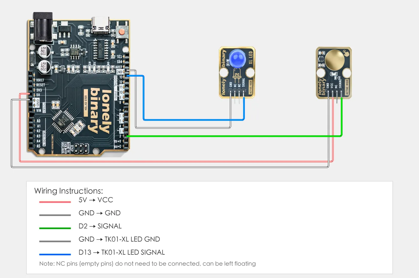
The output is a push-pull CMOS pin, so it drives the line both ways and needs
no pull-up or pull-down of its own. Declare the pin INPUT, not
INPUT_PULLUP.
The LED tells you it works before any code does
There is a red LED on the front with a 1 kΩ resistor, and it is wired across SIGNAL — not to a separate driver. That has a useful consequence: give the board power and nothing else, touch the pad, and the LED lights. No microcontroller, no sketch, no wiring beyond two leads.
It is worth doing first whenever a touch sensor seems dead, because it splits the problem cleanly in half. LED lights, but your program sees nothing: the fault is the SIGNAL wire or the pin number. LED does not light: the fault is power, or the pad, or the board.
Sensitivity, and what you can put in front of it
Three things set how sensitive the pad is, and only one of them is on the board.
The capacitor from the sense line to ground is what trims it. This board fits 22 pF, a middle value out of the 1–50 pF the chip accepts, and smaller is more sensitive. The pad area is fixed in the copper. The panel in front is the one you control: thinner is more sensitive, and the material must be non-conductive — Tontek's datasheet is explicit that this rules out metallic paint as well as metal. It gives no maximum thickness, so the only real test is the panel you actually plan to use.
Two things about the way it starts up are worth knowing before you blame the board.
It calibrates at power-up, and takes about half a second to do it. Whatever is near the pad during that half second becomes its idea of neutral, so a finger resting there at the moment you plug the USB in teaches it the wrong baseline. It also recalibrates continuously afterwards to follow slow changes in its surroundings, which is why a board that started out confused often comes good on its own — but a power-cycle with your hand clear is the quick fix.
It also sleeps between samples. Idle, it wakes about eight times a second and draws around 1.5 µA; touch it and it switches to sampling every 16 ms until about ten seconds after you let go. That is the difference between the two response figures in the table above: 46 ms when it is already awake, 160 ms for the first touch after it has been left alone. Neither is slow for a finger, but if you are timing something against the touch, it is the reason the first press of a session measures differently from the rest.
Example
// Pin number: change this to match your wiring
#define TOUCH_PIN 2      // Arduino digital pin connected to SIGNAL (e.g. D2)
#define LED_PIN 13       // LED pin (Arduino built-in LED on pin 13, or external LED)

void setup() {
  // Initialize pin modes
  pinMode(TOUCH_PIN, INPUT);   // Set touch sensor pin as input (to read detection state)
  pinMode(LED_PIN, OUTPUT);    // Set LED pin as output (to control LED on/off)

  // Start serial for debugging (9600 baud)
  Serial.begin(9600);

  Serial.println("Touch sensor program started");
  Serial.println("LED on when touch sensor is touched, LED off when not touched");
}

void loop() {
  // Read touch sensor state
  int touchState = digitalRead(TOUCH_PIN);  // Read sensor pin level: HIGH(1)=touched, LOW(0)=not touched

  // Control LED based on detection state
  if (touchState == HIGH) {
    // Touch sensor touched: LED on
    digitalWrite(LED_PIN, HIGH);
    Serial.println("Touch sensor - LED on");
  } else {
    // Not touched: LED off
    digitalWrite(LED_PIN, LOW);
    Serial.println("Not touched - LED off");
  }

  delay(100);  // Brief delay to avoid reading too fast
}# Import required modules
from machine import Pin # GPIO control
import time # For delay (time.sleep)
# Pin number: change these to match your wiring
TOUCH_PIN = 0 # GPIO connected to SIGNAL (e.g. GPIO 0)
LED_PIN = 1 # LED pin (GPIO 1, or external LED, Pico built-in LED is GPIO 25)
# Create pin objects
touch = Pin(TOUCH_PIN, Pin.IN) # Set touch sensor pin as input (to read detection state)
led = Pin(LED_PIN, Pin.OUT) # Set LED pin as output (to control LED on/off)
print("Touch sensor program started")
print("LED on when touch sensor is touched, LED off when not touched")
# Main loop: runs forever
while True:
# Read touch sensor state
touchState = touch.value() # Read sensor pin level: 1=touched (HIGH), 0=not touched (LOW)
# Control LED based on detection state
if touchState == 1:
# Touch sensor touched: turn LED on and print message
led.on() # Output HIGH, LED on
print("Touch sensor - LED on")
else:
# Not touched: turn LED off
led.off() # Output LOW, LED off
print("Not touched - LED off")
# Delay 100 milliseconds to avoid reading too fast
time.sleep_ms(100)When it doesn’t work
- Where is the jumper for toggle mode?
- This board does not have one. The chip's two option pins are soldered to ground in the copper, which selects active-high and momentary and nothing else. Tutorials that tell you to bridge a pad on the back are describing a different TTP223 board. Toggle is three lines of software — remember the last reading, and flip a variable when it goes from LOW to HIGH.
- It never triggers.
- Check you are on the right pin first: SIGNAL is the fourth one, not the third. The third is NC and is connected to nothing, so a wire there reads whatever the air is doing. If the wiring is right, something may have been resting on the pad through the half second after power-up, when the chip measures what neutral looks like. Take it off and power-cycle.
- It stays HIGH after I let go.
- Not toggle mode — this board cannot do toggle. Either something is still close enough to the pad to count, or the baseline drifted while something rested against it. Clear the area and power-cycle, and keep the SIGNAL lead away from anything that moves.
- It triggers on its own.
- A long lead is an antenna, and mains wiring a foot away is enough. Keep the wire to the pad short, do not run it alongside other wires, and give it a supply that does not sag — the datasheet warns that a supply shifting quickly causes false detections. The 100 nF capacitor it asks for is already fitted, so adding another one at the module is not the fix.
- Can I mount it behind a panel?
- Yes, and that is the point of it. The panel has to be non-conductive — no metal, including metallic paint — and thinner is more sensitive. Tontek does not publish a maximum thickness for this part, so the honest answer is to try it with the panel you actually intend to use.