Raspberry Pi Pico
RP2040 and RP2350 boards, in C or MicroPython. No WiFi unless it is a Pico W, but the PIO block does timing tricks nothing else at this price can.
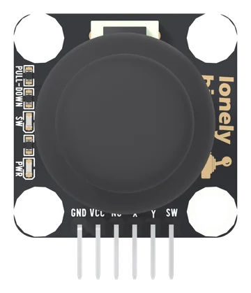
Dual Axis Joystick
A thumbstick on a square TinkerBlock board, on six pins: GND, VCC, NC, X, Y and SW. X and Y are two potentiometers from VCC to GND, read on analog pins; SW is the click under the stick, LOW at rest and HIGH when pressed, with its own pull-down. Every line reaches VCC, so VCC is your board's logic voltage. A PWR light and an SW light show power and each click.
INA219 and INA3221 Current Monitors: shunt, range and wiring
Two I²C current and voltage monitors: the TK119 with one INA219 on a 100 mΩ shunt, and the INA3221 with three channels on 50 mΩ. What the chip measures and what it works out, why the two resistors differ, the range and step each one gives, and the wiring for both.
SD and microSD Card Readers for ESP32: SPI, 1-bit and 4-bit
Two 3.3 V card reader boards with the SD bus brought out in full. What the two NC pins really are, which of SPI, 1-bit and 4-bit to use, what each measured, and the wiring for all three.
58mm Thermal Printers: the receipt kit, the label kit and the USB-C base board
Two thermal printer kits that share one Type-C TTL base board. The 9 V a USB port will not give you, which header your microcontroller belongs on, the baud rate printed on each unit, and the commands that put text, barcodes and labels on paper.
SPI TFT LCD Display Kit, 0.96 to 3.5 inch
Six colour SPI displays that are electrically one display: the same 15-pin ribbon, the same eight pads, the same eight wires. Which size to pick, how to wire it, and the one constant that swaps between them.
USB-C PD Trigger, 100 W Decoy 5–20 V
A USB-C charger holds 9, 12, 15 and 20 V and hands you 5 V until something asks. This board asks. Three levers set the voltage, a CH224K does the negotiating, and a screw terminal brings it out.
0.56-inch 7-Segment Digits with a 74HC595 Driver Board
A 24-pack of 0.56" seven-segment digits and twelve 74HC595 driver boards: three wires instead of eight, which digit is common cathode and which is common anode, how the ten pins line up, and the current limit that bites on 8.
10-Segment LED Bar Graph Display
Ten independent LEDs in one 20-pin package, with a resistor board that puts 220 Ω in front of each. Which way round it goes, why LOW lights a segment, and what ten of them at once costs an Arduino.
1602 I²C LCD Display Module, 16×2 Blue
A 16 × 2 character display with the I²C chip on the board rather than on a backpack. Four wires, address 0x27 by default, three solder pads to change it, and a contrast trimmer that explains most blank screens.
32x8 LED Matrix with MAX7219, 3-Pack
Four 8x8 squares in one strip, 256 LEDs, three signal wires. What the pads are called, why the sketch has to say four, and what to do about a 3.3 V board on a chip that wants 3.5 V.
4″ 7-Segment LED Display with 74HC595
A 100 mm digit with its own shift register on the back. Five wires from your board, a 12 V supply for the segments, and modules that plug into each other to make longer numbers.
ADS1115 16-Bit ADC I2C Module
Four analog inputs on two wires, with a real 16-bit converter and its own reference — the part you reach for when analogRead is not good enough. Which range to pick, why the supply is the real ceiling, and the two addresses this board can take.
Arcade Coin Acceptor Module Kit, USB-C Powered
A 12 V arcade coin acceptor and the USB-C board that runs it from one cable and hands your microcontroller a logic-level pulse. Up to six coin types, trained on real coins, counted on a single GPIO.
USB-C Breakout Board with 5.1 kΩ CC Resistors
A USB-C socket that a modern charger will actually talk to, with both CC pull-downs already fitted. What the resistors do, which of the six pads is which, how much current you may take, and the one thing the board can never be.
AMS1117 LDO Regulator Modules: 3.3 V and Adjustable
Eighteen fixed 3.3 V boards and six adjustable ones that turn a higher supply into a steady lower voltage. What to feed them, which pin is which, how much current before heat stops them, and how to set the adjustable board.
Logic Level Converters: MOSFET 2/4/6-Channel, TXB0108 and TXS0108
Five boards that let a 3.3 V board and a 5 V part share a wire safely. Which one to use for I²C, SPI, serial or an LED strip, which side is which, and the three wires that come before any signal.
Logic Analyzer Kit, 8-Channel 24 MHz
Eight channels sampled at up to 24 MS/s, straight up a USB cable. It decodes I²C, UART and SPI at the speeds a microcontroller actually runs, and the sample rate is the number that decides the rest.