
ESP32
The original dual-core WiFi and Bluetooth chip. Still the cheapest way to put a sensor on your network, and still what most library examples assume.
Turn it over: ESP32 Gold Edition in 3D
Electronics Starter Kit: Breadboard, Power Module and Loose Parts
A boxed set of the parts most breadboard circuits start with: an 830-point breadboard, a USB-C power module switchable between 3.3 V and 5 V, jumper wires, resistors, capacitors, LEDs, buttons, potentiometers, diodes, transistors, MOSFETs and two sensors. How to read the parts, set up the bench, and build the first circuits.
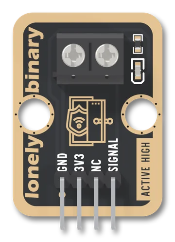
Door Sensor
A TinkerBlock board that takes the two bare wires of a magnetic door or window sensor on a screw terminal and puts it between VCC and SIGNAL. A closed sensor reads HIGH; open, SIGNAL floats, because the board has no pull-down, so you set one in setup(). The red LED lights while the sensor is closed: it is not a power light.
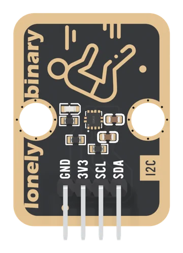
3-Axis Accelerometer
A Silan SC7A20H accelerometer on a TinkerBlock board: tilt, orientation, shakes and drops over two shared I²C wires, at address 0x19, with the pull-ups fitted. 3.3 V only.
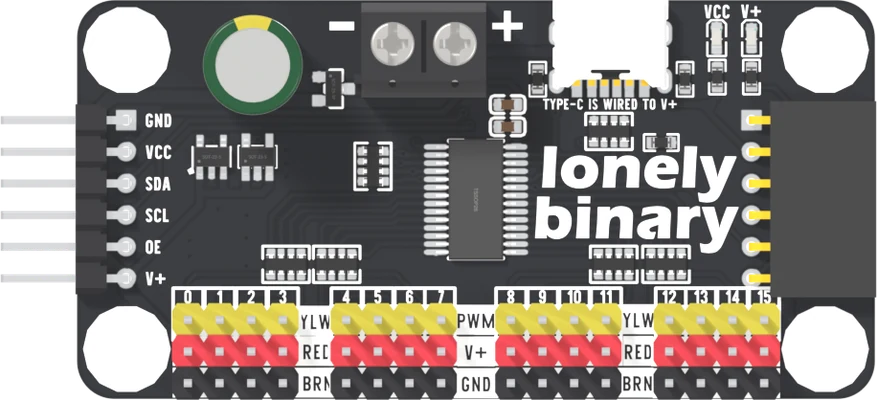
PCA9685 16-Channel Servo Driver: Sixteen Servos on Two I²C Wires
A PCA9685 board that keeps sixteen servo pulses running by itself while the microcontroller talks to it over I²C. Servo power on V+ from USB-C or a screw terminal, the chip on VCC, six address pads, and a header on each edge so boards plug into each other. Three boards a box, headers soldered.
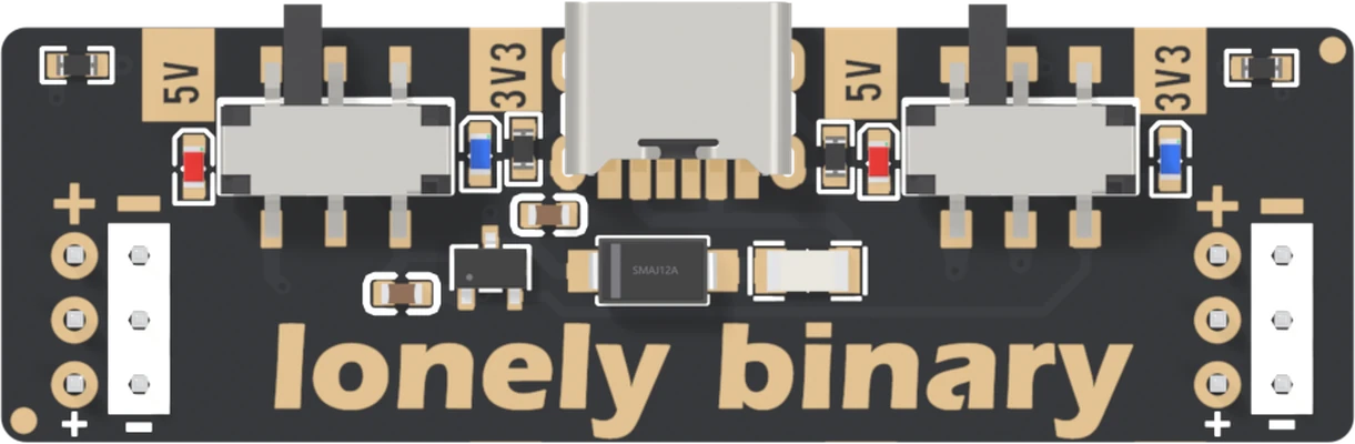
Breadboard Power Adapters: Standard 5 V / 3.3 V, Step-Down and Booster
Three USB-C breadboard power adapters that plug into both pairs of rails at one end: a standard board with a 5 V / 3.3 V switch per side, a step-down that sets 1.25 to about 3.5 V, and a booster that sets about 4.3 up to 28 V. Which way round they go, why 5 V reads 4.7, and the half-amp fuse that limits all three.
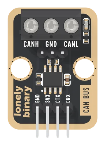
CAN Bus
An SN65HVD230 CAN transceiver on a TinkerBlock board, for 3.3 V microcontrollers with a CAN controller of their own, such as most ESP32 chips. CTX and CRX go straight across, the 120 Ω fitted on every board belongs only on the two end boards, GND runs with a twisted pair, and one board alone can never finish a message.
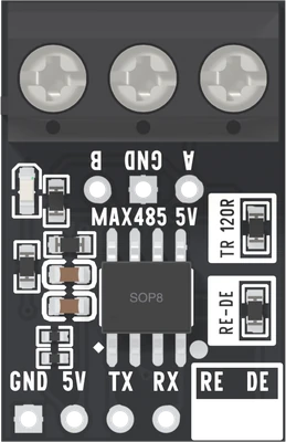
RS485 Transceiver Boards: MAX485 for 5 V and MAX3485 for 3.3 V
Two RS485 boards from one 12-pack: a MAX485 board for 5 V microcontrollers and a MAX3485 board for 3.3 V ones. The six pins, which board goes with your microcontroller, the 120 Ω fitted on every board that only the two end boards should keep, and RE joined to DE so one pin sets the direction.
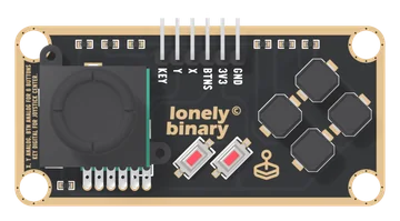
Slim Joystick
A thumb stick and six buttons on one long TinkerBlock board, on six pins. X and Y are two potentiometers, read on analog pins; KEY is the click under the stick, LOW at rest and HIGH when pushed; and all six buttons share BTNS, one analog pin, through a ladder of 10 kΩ resistors that gives each its own voltage. One button reads at a time.
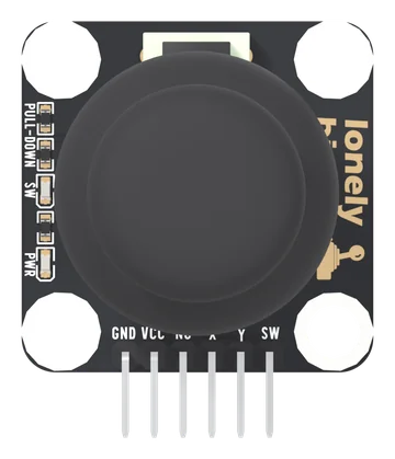
Dual Axis Joystick
A thumbstick on a square TinkerBlock board, on six pins: GND, VCC, NC, X, Y and SW. X and Y are two potentiometers from VCC to GND, read on analog pins; SW is the click under the stick, LOW at rest and HIGH when pressed, with its own pull-down. Every line reaches VCC, so VCC is your board's logic voltage. A PWR light and an SW light show power and each click.
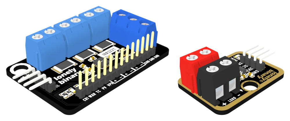
INA219 and INA3221 Current Monitors: shunt, range and wiring
Two I²C current and voltage monitors: the TK119 with one INA219 on a 100 mΩ shunt, and the INA3221 with three channels on 50 mΩ. What the chip measures and what it works out, why the two resistors differ, the range and step each one gives, and the wiring for both.
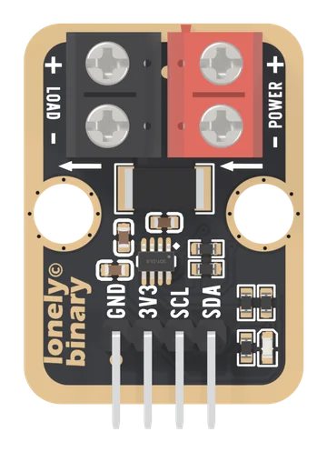
INA219 Current Monitor
A 100 milliohm resistor in the positive wire and a chip that reads the millivolts across it. Current, voltage and power over I²C, up to 3.2 A on a rail of up to 26 V.
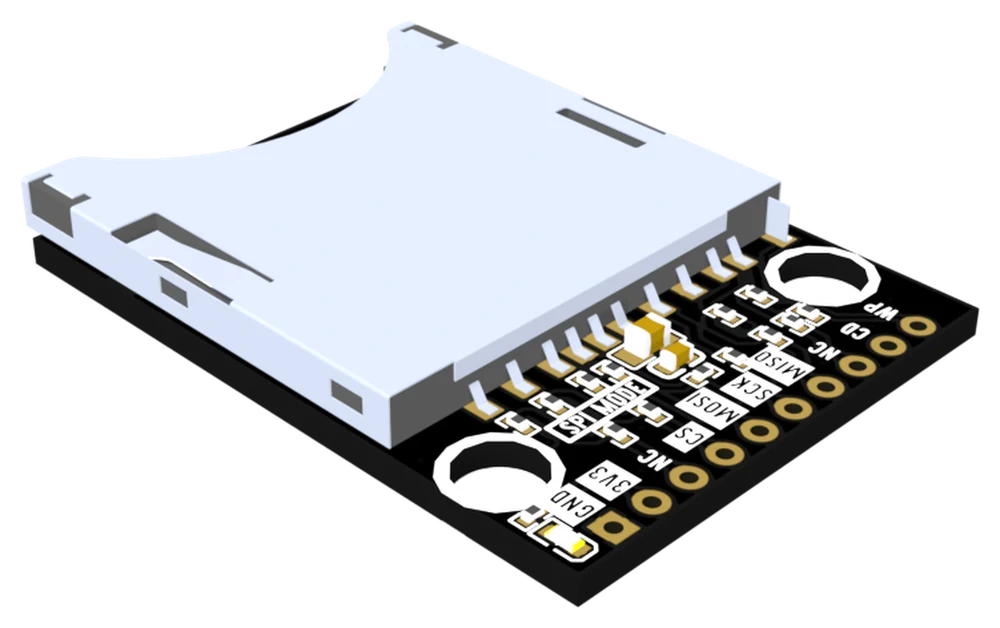
SD and microSD Card Readers for ESP32: SPI, 1-bit and 4-bit
Two 3.3 V card reader boards with the SD bus brought out in full. What the two NC pins really are, which of SPI, 1-bit and 4-bit to use, what each measured, and the wiring for all three.
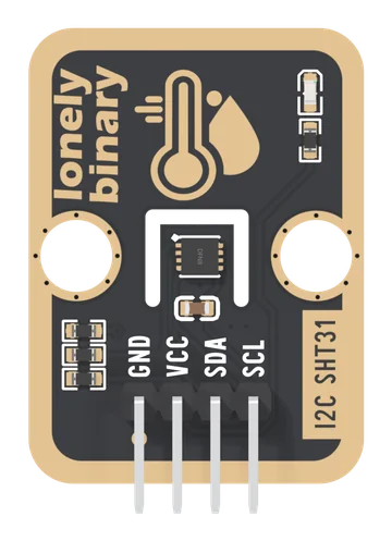
SHT31 Temperature and Humidity Sensor
A Sensirion SHT31 on a TinkerBlock carrier: two numbers over two shared wires, calibrated at the factory, with the pull-ups already fitted and two jumpers on the back that set the address and take them away again.
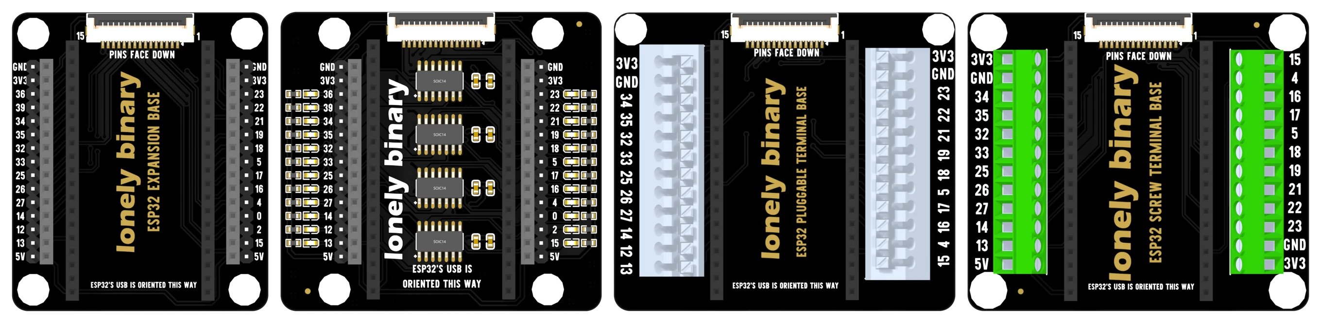
ESP32 Expansion Bases: 2.54 mm, PinPulse, Pluggable Terminal and Screw Terminal
Four bases for the 38-pin Lonely Binary ESP32. Which pins each one brings out, which way round the board goes, the fifteen-way display port they all share, and the twenty-four LEDs on the PinPulse.
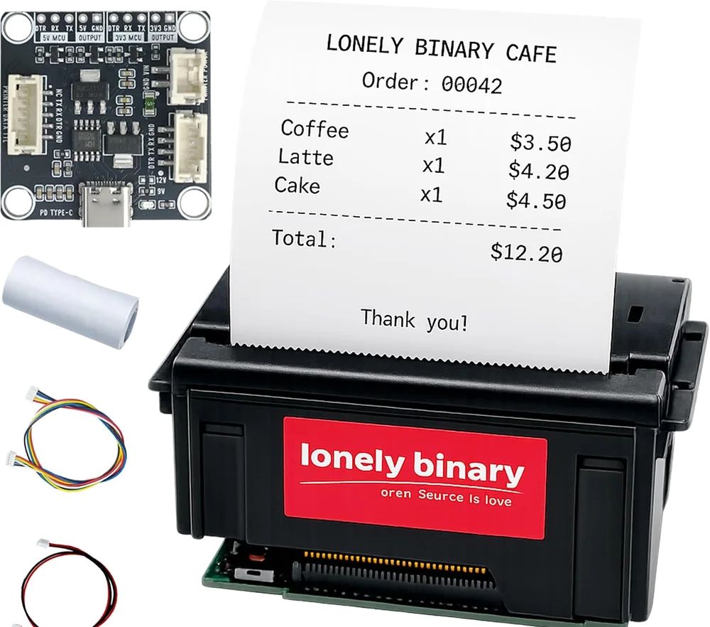
58mm Thermal Printers: the receipt kit, the label kit and the USB-C base board
Two thermal printer kits that share one Type-C TTL base board. The 9 V a USB port will not give you, which header your microcontroller belongs on, the baud rate printed on each unit, and the commands that put text, barcodes and labels on paper.
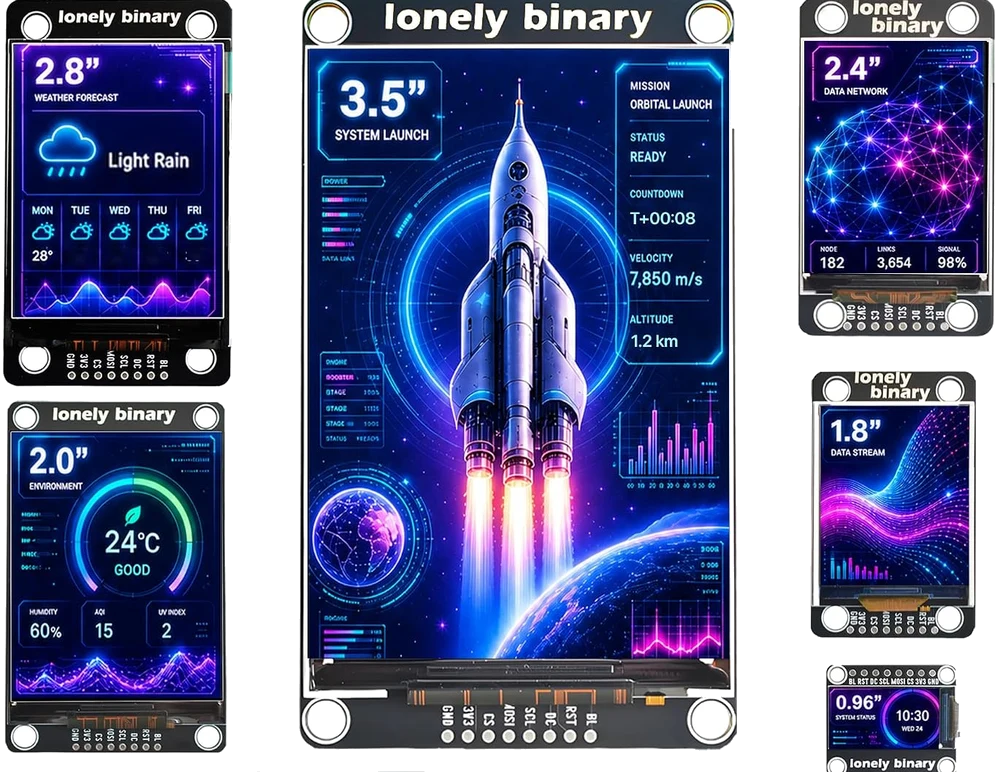
SPI TFT LCD Display Boards, 0.96 to 3.5 inch
Six colour SPI display boards that are one circuit on six outlines: the same eight holes, the same 15-way ribbon socket, a backlight switched by a transistor, and a driver library that takes one constant per size. Which size to pick, how to wire it, and what is different about each.
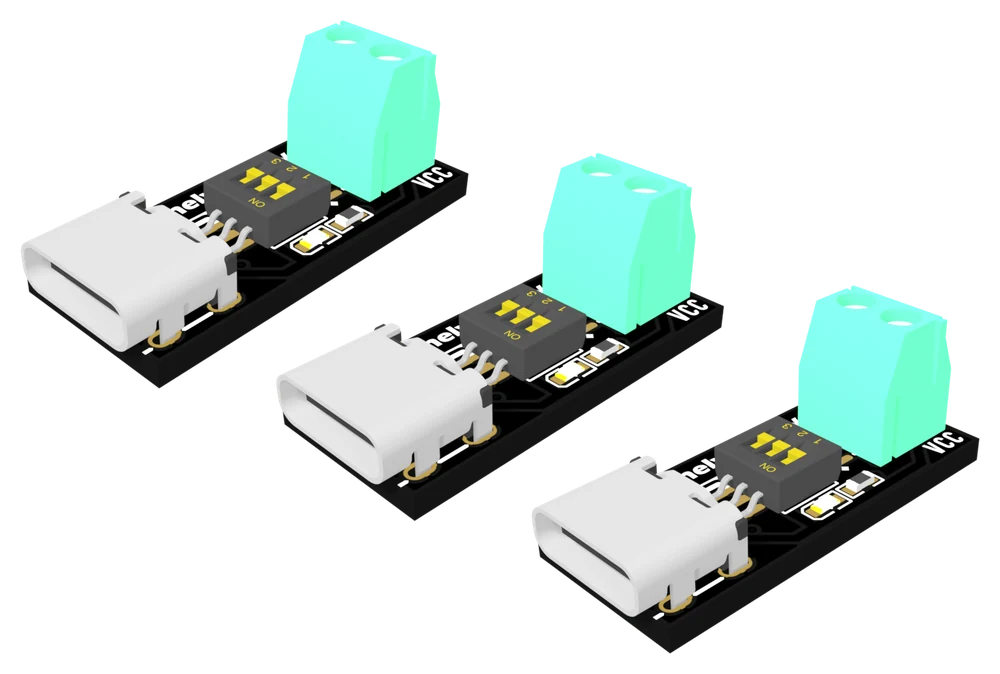
USB-C PD Trigger, 100 W Decoy 5–20 V
A USB-C charger holds 9, 12, 15 and 20 V and hands you 5 V until something asks. This board asks. Three levers set the voltage, a CH224K does the negotiating, and a screw terminal brings it out.
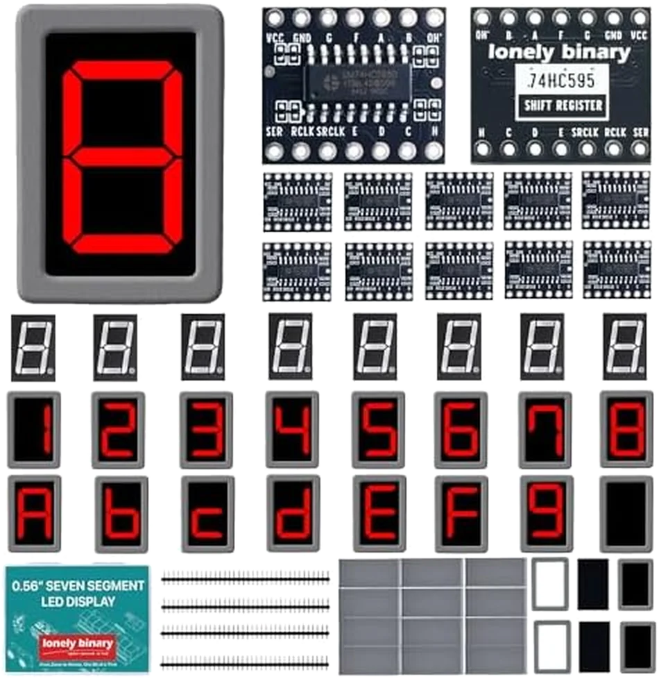
0.56-inch 7-Segment Digits with a 74HC595 Driver Board
A 24-pack of 0.56" seven-segment digits and twelve 74HC595 driver boards: three wires instead of eight, which digit is common cathode and which is common anode, how the ten pins line up, and the current limit that bites on 8.
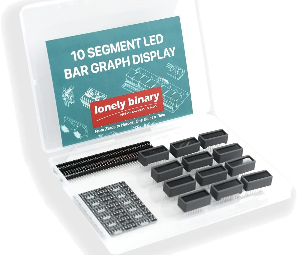
10-Segment LED Bar Graph Display
Ten independent LEDs in one 20-pin package, with a resistor board that puts 220 Ω in front of each. Which way round it goes, why LOW lights a segment, and what ten of them at once costs an Arduino.
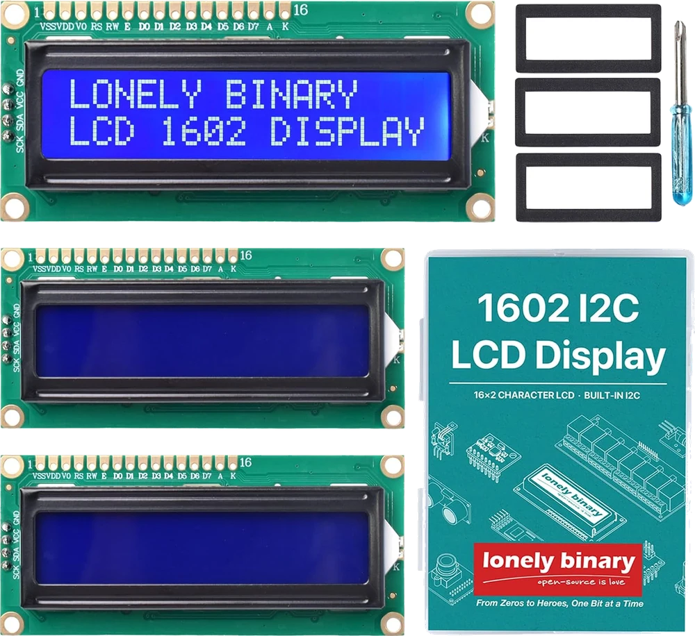
1602 I²C LCD Display Module, 16×2 Blue
A 16 × 2 character display with the I²C chip on the board rather than on a backpack. Four wires, address 0x27 by default, three solder pads to change it, and a contrast trimmer that explains most blank screens.
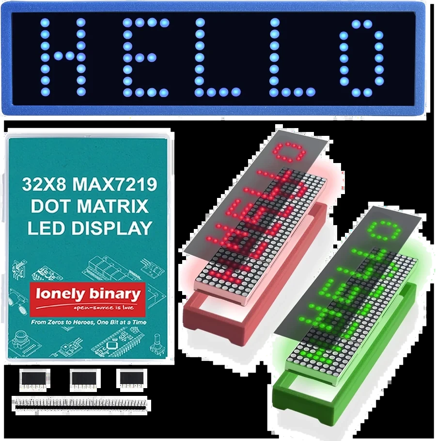
32x8 LED Matrix with MAX7219, 3-Pack
Four 8x8 squares in one strip, 256 LEDs, three signal wires. What the pads are called, why the sketch has to say four, and what to do about a 3.3 V board on a chip that wants 3.5 V.
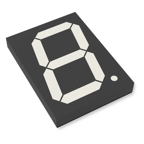
4″ 7-Segment LED Display with 74HC595
The newer 4-inch digit, with a PWM pad for dimming (the earlier version had none). Its own shift register, six signal wires from your board, a 12 V supply for the segments, and modules that plug into each other to make longer numbers.
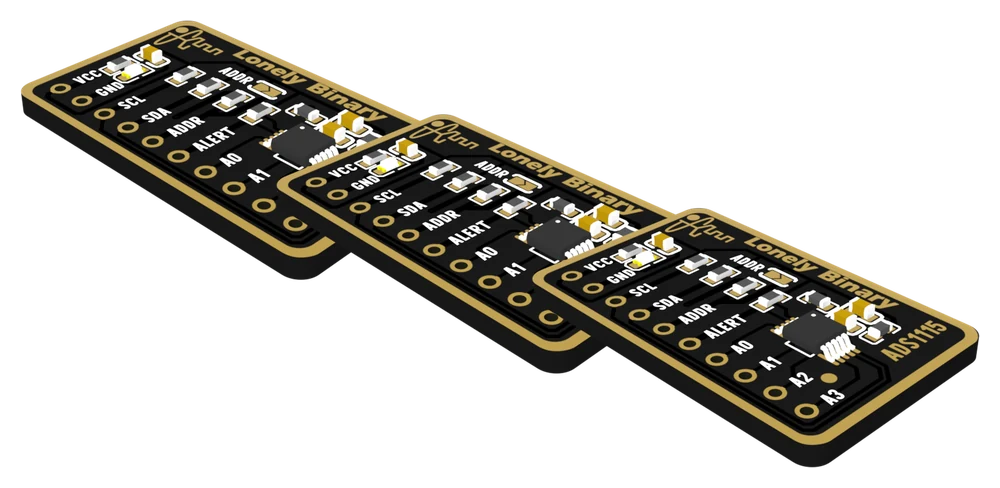
ADS1115 16-Bit ADC I2C Module
Four analog inputs on two wires, with a real 16-bit converter and its own reference — the part you reach for when analogRead is not good enough. Which range to pick, why the supply is the real ceiling, and the two addresses this board can take.
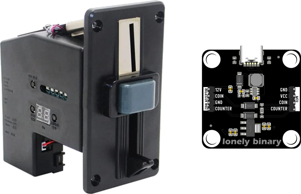
Arcade Coin Acceptor Module Kit, USB-C Powered
A 12 V arcade coin acceptor and the USB-C board that runs it from one cable and hands your microcontroller a logic-level pulse. Up to six coin types, trained on real coins, counted on a single GPIO.
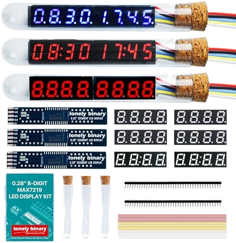
MAX7219 Vintage Tube LED Clock Kit
Eight 0.28-inch digits on a MAX7219, in a glass tube with a cork. Three displays arrive built and three arrive as pieces — a driver board and two four-digit panels, in red or blue, with a colon or with decimal points.
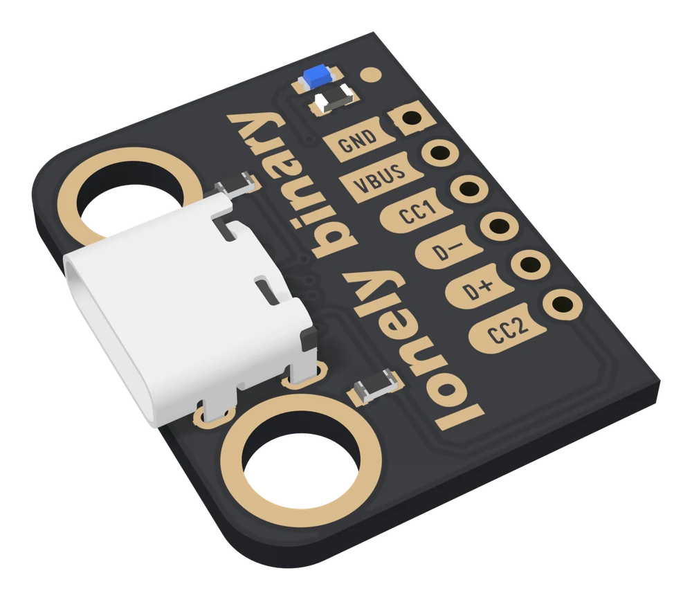
USB-C Breakout Board with 5.1 kΩ CC Resistors
A USB-C socket that a modern charger will actually talk to, with both CC pull-downs already fitted. What the resistors do, which of the six pads is which, how much current you may take, and the one thing the board can never be.
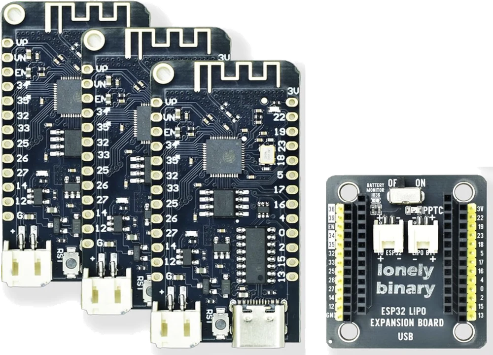
ESP32 LiPo Dev Kit: 3 Boards with a LiPo Charger, and 3 Shields
Three classic ESP32 boards that charge a lithium cell from USB-C and run from it when the cable comes out, and three shields to wire them on. Which cell, which socket, which way round, and how long a cell lasts.
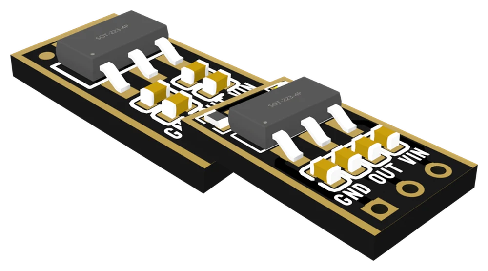
AMS1117 LDO Regulator Modules: 3.3 V and Adjustable
Eighteen fixed 3.3 V boards and six adjustable ones that turn a higher supply into a steady lower voltage. What to feed them, which pin is which, how much current before heat stops them, and how to set the adjustable board.
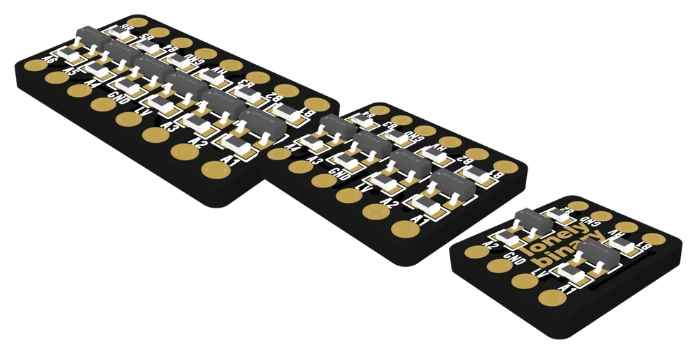
Logic Level Converters: MOSFET 2/4/6-Channel, TXB0108 and TXS0108
Five boards that let a 3.3 V board and a 5 V part share a wire safely. Which one to use for I²C, SPI, serial or an LED strip, which side is which, and the three wires that come before any signal.
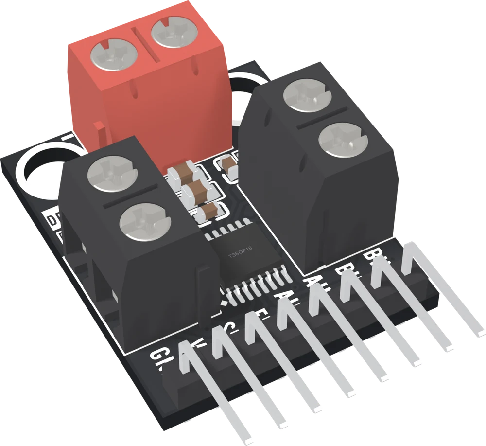
DRV8833 Dual Motor Driver
Two DC motors, or one stepper, from four GPIO pins. The board ships bare, the sleep pin is asleep until you drive it, and the red LED only says the supply is there.
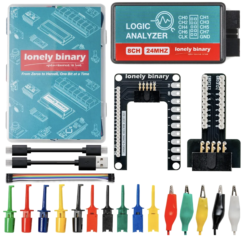
Logic Analyzer Kit, 8-Channel 24 MHz
Eight channels sampled at up to 24 MS/s, straight up a USB cable. It decodes I²C, UART and SPI at the speeds a microcontroller actually runs, and the sample rate is the number that decides the rest.
ESP32 Gold Edition pinout
All 38 holes on the Lonely Binary ESP32 Gold Edition — the four that can only ever be inputs, the five sampled at reset, and the six that are drilled, labelled and wired to nothing.
1.8-inch TFT Display
A 1.77-inch colour TFT, 128 by 160 pixels, with an ST7735S controller on SPI, on a TinkerBlock board with an eight-pin header. 3.3 V only, with nothing on the board to shift 5 V signals down: an Uno goes through a TK97. The backlight stays off until BL is driven HIGH.
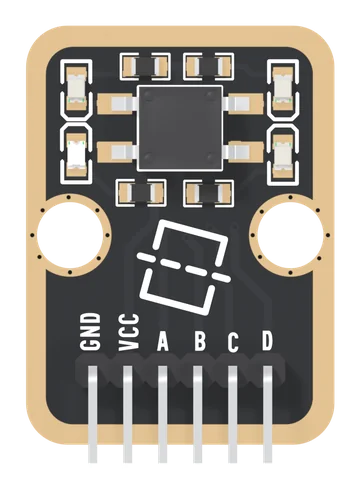
4-Direction Tilt Sensor
One metal roller in a square switch with four corner contacts, on a TinkerBlock board: tip an edge down and the roller joins that side's two lines. Your board finds which pair by holding one line LOW and reading who follows. Four answers and none, no angle, and four red LEDs that light when a line is held LOW.
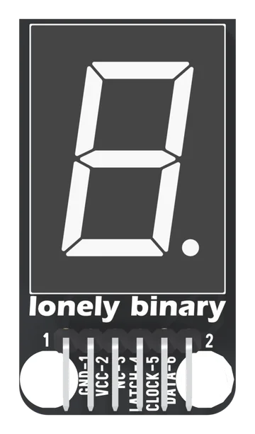
74HC595 Segment LED
One 0.8-inch red seven-segment digit with a 74HC595 shift register under it, on a TinkerBlock board: three wires set all eight segments, one byte per digit, a 1 lights a segment. Common cathode, 150 Ω per segment, VCC on your board's logic supply, and no chaining: the 595's serial output is not connected.
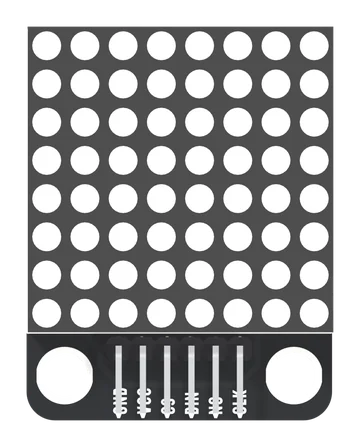
8x8 LED Matrix
Sixty-four red LEDs and a MAX7219 that scans them for you, on the TinkerBlock TK52: five wires, VCC on 5 V, a picture sent as eight bytes. The page is shared with the chainable 3-pack module, and only that one can be chained: the TK52 has no DOUT.
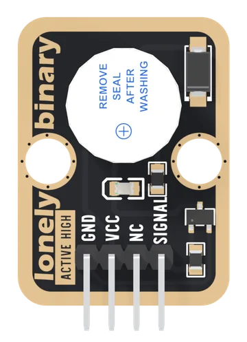
Active Buzzer
A 12 mm electromagnetic buzzer with its own oscillator, on a TinkerBlock board. SIGNAL HIGH beeps at about 2.4 kHz, LOW stops it: one note, one line of code. An S8050 transistor switches it from VCC, so your pin gives a few milliamps and VCC can be 5V beside a 3.3 V board. There is no pull-down on SIGNAL, so use a pin that stays LOW while your board boots.
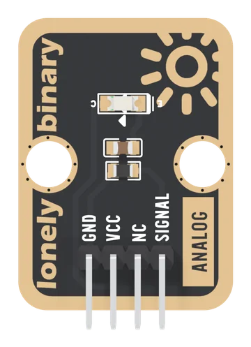
Ambient Light Sensor
A phototransistor and a 4.7 kΩ resistor on a TinkerBlock board: light makes a current, the resistor turns it into a voltage, and SIGNAL rises with the light. A lit room reads low on the scale, bright light flattens just under VCC, and it sees near infrared best.
Analog Microphone
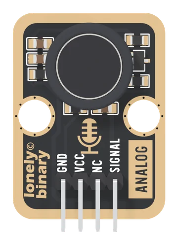
An electret capsule and a one-transistor amplifier on a TinkerBlock board. SIGNAL rests at a level set by the transistor's gain and swings above and below it with sound, in a band of roughly 75 Hz to 1 kHz. Read the peak-to-peak over 50 ms: it hears claps, knocks and loud voices, and it is not a recording microphone.
Analog to Digital Signal
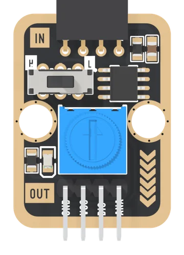
An LM393 comparator on a TinkerBlock board: plug an analog block into the IN socket, set a threshold with the blue knob, and DIG tells your board whether the block's voltage is above or below it. The block's own voltage passes through on ANA, and a slide switch printed H and L turns the answer over.
Collision Sensor
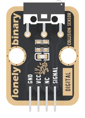
A lever microswitch with its 10 kΩ pull-down and a red hit light already fitted: SIGNAL reads HIGH while the lever is pushed in. The bumper for a TinkerBlock robot, and the sense that never reports a wall that is not there.
DHT11 Temperature and Humidity Sensor
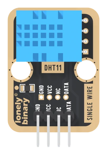
A DHT11 on a TinkerBlock board, the TK38: temperature from 0 to 50 °C to ±2 °C and humidity from 20 to 80 % to ±5 %, in whole numbers, on one data wire. The 10 kΩ pull-up is fitted, so it is three wires and one library. Feed VCC what your board's pins run at: the pull-up ties DATA to it.
Disc Potentiometer
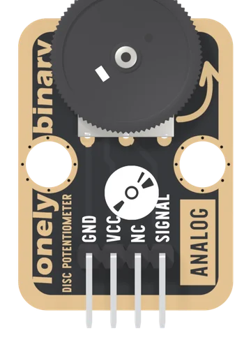
A 10 kΩ thumbwheel potentiometer wired as a voltage divider: turn the wheel and SIGNAL runs from 0 V to VCC, read by one analog pin. The wheel lies flat and overhangs the board's edge, so a thumb turns it from the side.
Dual Bright LEDs
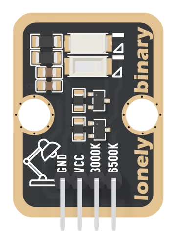
Two 5730-size white LEDs on a TinkerBlock board, one warm (3000K) and one cool (6500K), each switched by its own S8050 transistor with a 10 Ω resistor from VCC. A pin for each colour, PWM for brightness and for every white between the two. VCC may be 5 V on a 3.3 V board; on 5 V, cap the PWM at two thirds.
EEPROM Memory
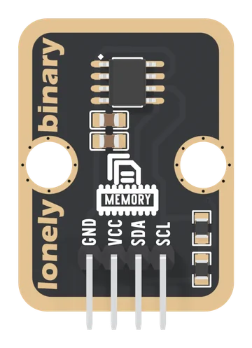
An AT24C128 I2C EEPROM on a TinkerBlock board: 16,384 bytes that keep their values with the power off, at address 0x50. VCC goes to your board's logic supply because the pull-ups end at VCC, each write takes up to 5 ms, a write wraps inside its 64-byte page, and each byte takes about a million writes.
Five-Direction Joystick
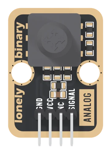
A five-way navigation switch on one analog pin: four tilts and a press, each joining SIGNAL to its own point of a chain of 10 kΩ resistors, so each push is its own voltage. Read it with analogRead, not digitalRead. VCC is your board's logic voltage.
Hall Effect Sensor
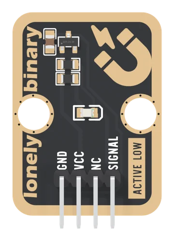
An omnipolar Hall switch on a TinkerBlock board: bring either pole of a magnet near and SIGNAL goes LOW and a red light comes on. No contact to wear out, it works through plastic, and it looks at the field every 22 ms, so it is made for doors, lids and slow wheels.
Infrared Receiver
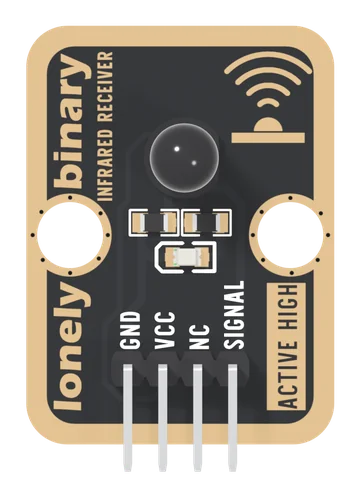
An infrared light sensor on a TinkerBlock board: an Everlight PT334-6B phototransistor in a black 5 mm package and a 10 kΩ load, so SIGNAL is an analog voltage that rises with how much infrared arrives, steady or flashing. The partner of the TK63 for a break-beam. It is not the TK15 IR Receiver: it decodes no remote, and the TK15 ignores steady light.
Infrared Speed Sensor
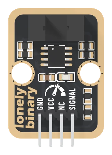
A GK105A slotted optical switch on a TinkerBlock board: an infrared beam across a 5 mm slot, judged by an LM393 comparator. Something in the slot reads HIGH; a clear slot reads LOW and lights a red LED. Put a slotted disc through it and count pulses for rpm, up to about 1,900 a second. VCC must be your board's logic voltage.
Infrared Transmitter
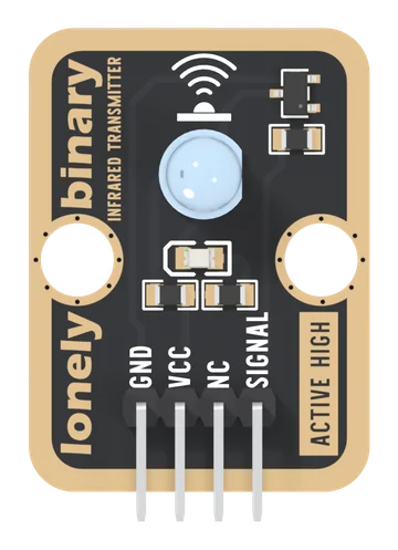
A 5 mm, 940 nm infrared LED on a TinkerBlock board, switched by an S8050 transistor, with one 150 Ω resistor setting its current from VCC and a red LED that shows when it is on. SIGNAL HIGH turns it on. Your pin only feeds the transistor, so VCC may be 5 V on a 3.3 V board. Blink it, send remote-control codes to a TK15, or make a break-beam with a TK64.
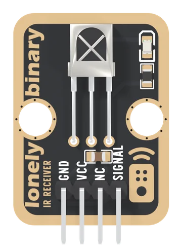
IR Receiver
A Vishay TSOP18138 38 kHz infrared receiver on a TinkerBlock board: SIGNAL idles HIGH and goes LOW while a remote sends, and the IRremote library turns those lows into an address and a command.
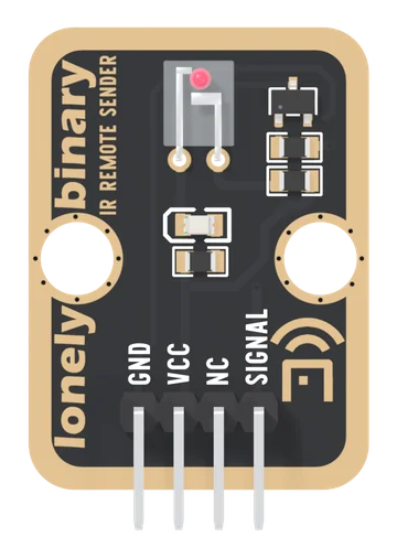
IR Sender
An Everlight IR908-7C 940 nm infrared LED, switched by a transistor, on a TinkerBlock board. SIGNAL HIGH lights it; your microcontroller makes the 38 kHz carrier, and one 150 Ω resistor decides how far it reaches.
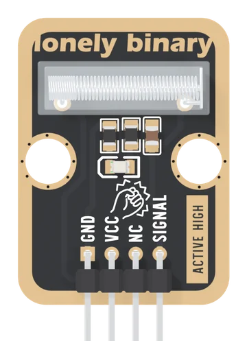
Knock Sensor
A spring vibration switch with its 10 kΩ pull-down, a 100 nF capacitor and a red flash light already fitted: SIGNAL goes HIGH for a moment each time a knock swings the spring onto its rod. A tap on a table as a button, a door that was knocked, a box that was dropped.
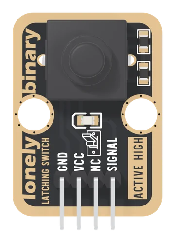
Latching Button
A push-on, push-off switch with its pull-down and a red indicator LED already fitted: one press turns SIGNAL HIGH and it stays HIGH, through a reset or a power cut, until the next press.
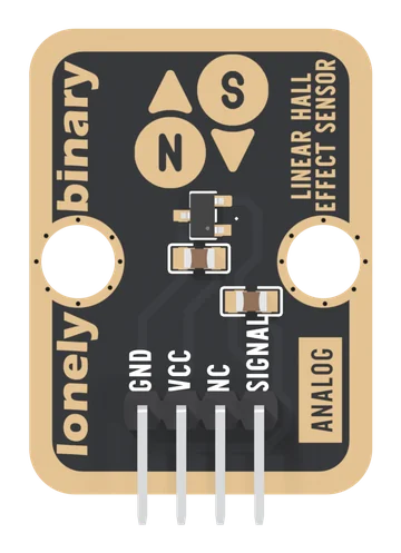
Linear Hall Effect Sensor
An SS49E-type linear Hall sensor on a TinkerBlock board: an analog voltage that rests at half of VCC with no field and moves about 3.25 mV per gauss at 5 V, up for one pole and down for the other. It tells you how strong a magnetic field is and which way it points. VCC must be your board's logic voltage, and it is not a current sensor on its own.
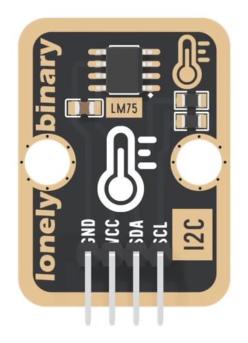
LM75 Temperature Sensor
An LM75B digital temperature sensor on a TinkerBlock board, read over I2C at address 0x48: two bytes that are already degrees, in steps of an eighth, within 2 °C from −25 to 100 °C. VCC goes to your board's logic supply because the pull-ups end at VCC.
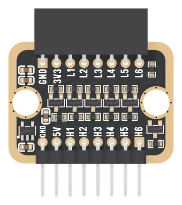
Logic Level Converter
Six bidirectional channels between 3.3 V and 5 V on a TinkerBlock board: L1 to L6 in a socket on the 3.3 V side, H1 to H6 on a header on the 5 V side, each a BSS138 with a 10 kΩ pull-up either side. It needs only 5V and GND: an ME6211 regulator makes the 3.3 V side's supply, so the socket's 3V3 pin is an output that powers a 3.3 V block, and is never fed.
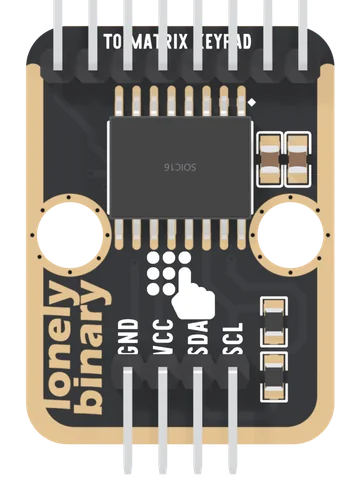
Matrix Keypad with I2C Adapter (4x4, PCF8574)
A 4×4 keypad on two I²C wires instead of eight GPIO pins. The TK85 adapter at a fixed 0x20, the compact adapter in the keypad packs with eight addresses, the soft and heavy-duty keypads, and the two keymaps they need.
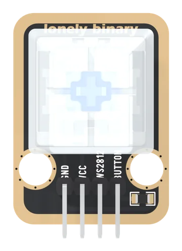
Mechanical Key and LED
A keyboard switch with a WS2812 RGB LED under its clear keycap, as two separate circuits: the key reads HIGH when pressed through its own 10 kΩ pull-down, and the LED shows whatever colour your sketch sends it. VCC is your board's logic voltage.
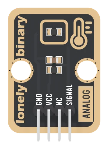
NTC Thermistor
A 10 kΩ NTC thermistor in a divider with a fixed 10 kΩ: SIGNAL is half of VCC at 25 °C and falls as it warms. Read it on any analog pin and turn it into degrees with two lines of arithmetic.
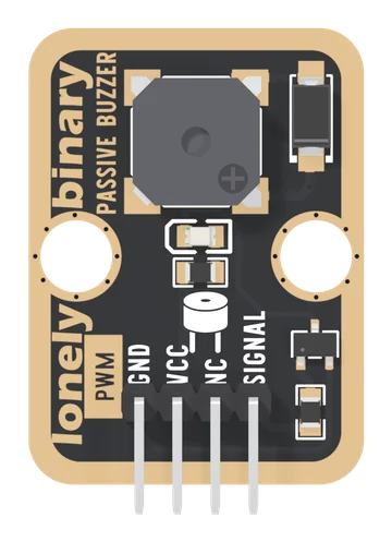
Passive Buzzer
A magnetic buzzer with no oscillator of its own, switched by a transistor on a TinkerBlock board. It sounds only while SIGNAL is a square wave, at the wave's frequency, so tone() plays any note; it is loudest at its 2.7 kHz resonance. Held HIGH it is silent and the coil draws about 200 mA.
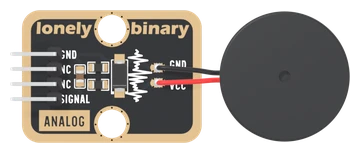
Piezo-Ceramic Sensor
A 22 mm piezo disc on a TinkerBlock board that needs no supply: two wires, GND and SIGNAL. A tap makes a hump on SIGNAL that rises in about a millisecond and drains in about a tenth of a second, taller for a harder tap. It senses change, not weight, and nothing on the board holds SIGNAL below 3.3 V.
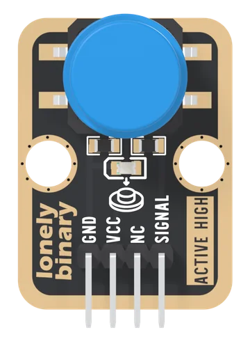
Push Button
A 12 mm momentary push button with its 10 kΩ pull-down and a red press light already fitted: SIGNAL reads HIGH while the button is down. The first input in the kit, and the module that teaches debouncing.
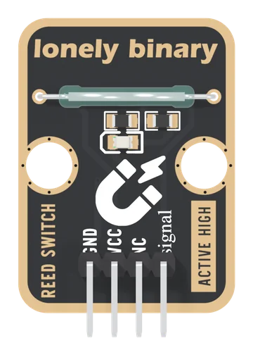
Reed Switch
A glass reed switch on a TinkerBlock board: two blades that a magnet pulls shut, from either pole, with no power needed to sense. It sits between VCC and SIGNAL with a 10 kΩ pull-down, so a magnet reads HIGH, and a red LED lights while it is closed. It draws nothing while open, and VCC must be your board's logic voltage.
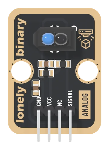
Reflective Optical Sensor
A Vishay TCRT5000 on a TinkerBlock board: an infrared emitter that is always on and a phototransistor beside it, both looking out of the front. Infrared coming back pulls SIGNAL down from VCC through 4.7 kΩ, so white paper reads low and black tape or open air reads high. Analog only, best at 2.5 mm, and VCC goes to your board's logic voltage: 3V3, or 5V on an Uno.
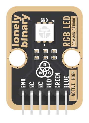
RGB LED
A red, a green and a blue LED in one 5 mm package, each with its own 1 kΩ resistor and its own pin, joined at a common cathode. Three PWM pins mix any colour, and the handbook works out why three equal numbers are not white.
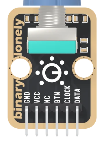
Rotary Encoder
An EC11-type rotary encoder with a push switch in its shaft, its pull-ups, filter capacitors and pull-down already fitted. Two contacts a quarter of a cycle apart give the direction; the program keeps the count. Pushed in, BTN reads HIGH.
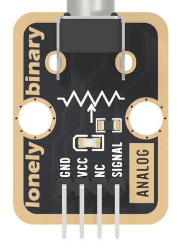
Rotary Potentiometer
A 10 kΩ linear potentiometer with a knob, wired as a voltage divider: SIGNAL gives 0 V to VCC as you turn. A red LED on the wiper glows as you turn up, and it bends the upper part of the reading: hard on 5 V, less on 3.3 V.
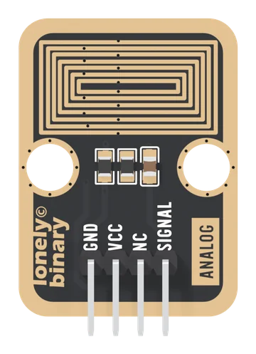
Steam Sensor
A TinkerBlock board that reads water on its surface: seven nested loops of bare gold, every other one on VCC, the rest held at 0 V by a 1 MΩ. Condensed steam, breath or a drop across the loops makes a divider, and SIGNAL rises from 0 V towards VCC. It is an analog output, it does not sense humidity in the air, and VCC must be your board's logic voltage.
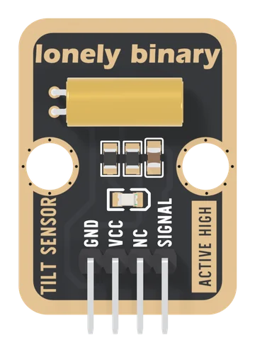
Tilt Sensor
An SW-520D ball tilt switch on a TinkerBlock board: two steel balls in a brass can that close the switch when its lead end, the board's left edge, is the lower one. It sits between VCC and SIGNAL with a 10 kΩ pull-down and a 100 nF, so left edge down reads HIGH, and a red LED lights while it is closed. It draws nothing while open, reads nothing definite near level, and VCC must be your board's logic voltage.
TinkerBlock
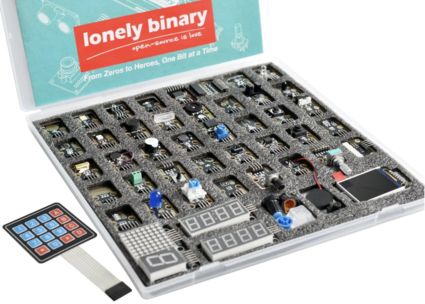
Our own modular series — sensors, displays and actuators that share one pin convention, one numbering scheme, and one set of wiring habits.
TinkerBlock 46-Piece Sensor Module Kit
Forty-four modules on gold-plated breakouts, sharing one pin convention — and the forty-five-lesson workshop written around them.
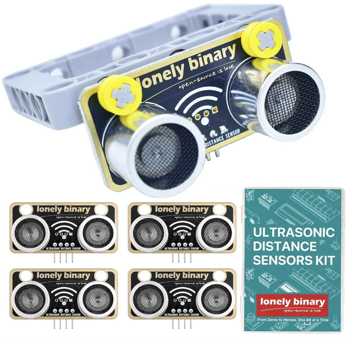
TinkerBlock Ultrasonic Distance Sensor Kit
Distance by echo timing, five to a pack — enough for a robot with a sensor on every side.
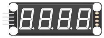
TM1637 4-Digit Display (0.56 inch)
Four seven-segment digits on two ordinary pins. The TinkerBlock TK51 with its clock colon, the clock set, the digit set with decimal points, and the one bit that behaves differently on each.
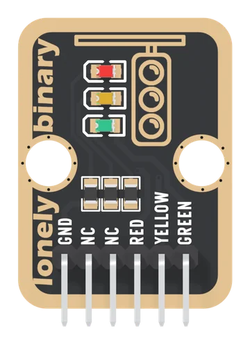
Traffic Light
Red, yellow and green LEDs, each with its own 1 kΩ resistor and its own pin, sharing one GND: three digital outputs, and the first sketch that has to remember what it is doing.
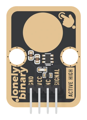
TTP223 Touch Sensor
A 12 mm gold pad and a TTP223 touch chip on a TinkerBlock board: SIGNAL is HIGH while a finger is on the pad, through plastic or glass as well as bare, and LOW the rest of the time. Momentary and active-high in copper, with no jumper. SIGNAL is the chip's own output from VCC, so VCC goes to your board's logic supply, and the pad must be left alone for the half second after power-up.
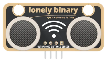
Ultrasonic Distance Sensor
Distance by echo timing, on an RCWL-9616 that runs from 3 to 5 V and speaks GPIO, I2C, UART or 1-Wire, chosen by two solder jumpers. No divider on a 3.3 V board. Soft and angled surfaces are where it quietly lies to you.
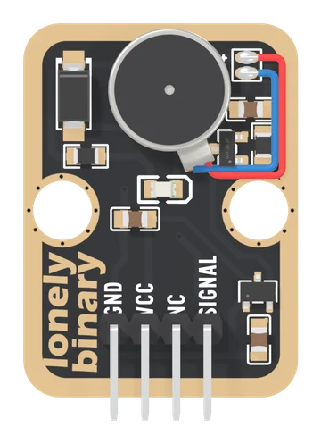
Vibration Motor
A 10 mm coin vibration motor on a TinkerBlock board, switched by a MOSFET and fed from the board's own 3.3 V regulator. SIGNAL HIGH buzzes, LOW stops, analogWrite sets the strength. VCC only feeds the regulator, so 5V on VCC is safe beside a 3.3 V board, and 3V3 or 5V both give the motor about 3.3 V.
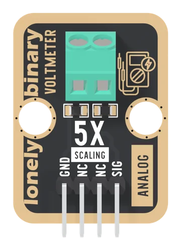
Voltmeter
A 30 kΩ and 7.5 kΩ divider behind a two-screw terminal: SIG is exactly one fifth of the input, so an analog pin can read up to 25 V on a 5 V board and about 15.5 V on a 3.3 V one. DC only, measured from GND.
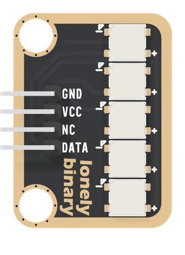
WS2812 RGB LED Bar
Five addressable RGB LEDs on one data wire. VCC wants 5 V, each colour runs at 12 mA, the LEDs read green first, and the chain ends at the fifth LED.
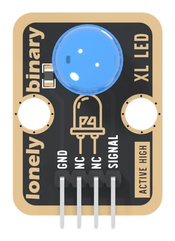
XL LED
A 10 mm blue LED with its 150 Ω resistor already fitted, driven by one pin: the first output most people ever drive, and the light every later lesson uses to show that something happened.
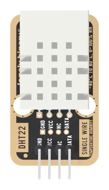
DHT22 Temperature and Humidity Sensor
A DHT22 on a TinkerBlock board, the TK39: temperature from −40 to 80 °C to ±0.5 °C and humidity from 0 to 100 % to ±2 %, in tenths, on one data wire. The 10 kΩ pull-up is fitted, so it is three wires and one library. Feed VCC what your board's pins run at, and read it no more than once every two seconds.