Specifications
| Type | Four-direction tilt switch: one roller, four corner contacts. It joins two neighbouring lines, never a line to GND |
|---|---|
| Switch | RB-6635S-1T, 6 × 6 × 3.5 mm SMD, in the upper middle of the board |
| Directions | 4 plus none: left edge down joins A–B, top B–C, right C–D, header edge D–A. A–C and B–D never join |
| Reading it | A scan: hold A LOW and read B and D, then hold C LOW and read them again. Every line INPUT_PULLUP otherwise, never OUTPUT HIGH |
| Level | Not a reading: the roller stays where it last rolled, and a corner can read none |
| Indicators | 4 red LEDs, one per line, each with 1 kΩ from VCC. Lit only while its line is held LOW: about 3 mA from 5 V, 1.3 mA from 3.3 V |
| Supply | 3.3 V or 5 V on VCC, matching your board: 3V3 beside an ESP32, ESP32-S3 or Pico, 5V beside an Uno. VCC feeds only the LEDs |
| Pins to wire | All 6: GND, VCC and four GPIOs for A, B, C and D. No NC pin |
| Header | 6-pin right-angle male, 2.54 mm pitch: GND, VCC, A, B, C, D, with GND on the square pad |
| Board | 22.4 × 30.4 mm, two 4.8 mm mounting holes 16 mm apart |
| In the box | 1 × TK19 block. It also ships inside the TinkerBlock kits |
What it is
A square tilt switch with a metal roller inside, four red LEDs, and a six-pin header. Tip one edge of the board down and the roller rolls to that side of its cell and joins the two contacts there. Each contact is one of the lines A, B, C and D, so the four edges are four pairs: A–B, B–C, C–D and D–A.
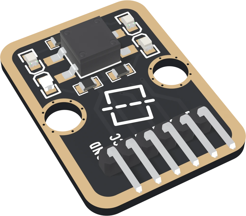
It is not an accelerometer. It has four answers and none, no angle, and it cannot say level: the roller stays wherever it last rolled. For "which edge is down" or "has this box been tipped over", that is enough.
The page this replaces said it was four balls in four tubes, that each pin can be read on its own, that a flat board is a neutral state, and that two sides can both be closed near a diagonal. None of that is true of this switch.
You cannot read it like a button
Nothing on the board goes to GND. The roller only joins two lines to each
other, so four pins set to INPUT_PULLUP read HIGH whichever way it leans.
Your board finds the pair with a small scan:
- Hold A LOW, read B and D. B LOW: left edge down. D LOW: header edge down.
- Let A go, hold C LOW, read B and D. B LOW: top edge down. D LOW: right edge down.
- Let everything go.
A released line is always an input with its pull-up, never an output driven HIGH, because the roller could join it to a line held LOW.
Which pin is which
Parts up, header at the bottom, reading left to right:
| GND | to your board's GND | the square pad: count from here. Reaches nothing on the board; it is the common ground |
| VCC | to 3V3 or 5V | your board's logic voltage. Feeds the four LEDs only |
| A | to a GPIO | lower-left leg of the switch |
| B | to a GPIO | upper-left leg |
| C | to a GPIO | upper-right leg |
| D | to a GPIO | lower-right leg |
The back prints TK19 4-DIRECTIONS TILT SENSOR and no pin names. Turned over, the square pad is on the right, and it is still GND.
The lights, and VCC
Each line has a red LED from VCC through 1 kΩ, lit only while that line is held LOW. With only power wired they stay dark. Holding a line LOW lights its LED at:
| Your board | VCC to | Per lit LED |
|---|---|---|
| Arduino Uno | 5V | about 3 mA |
| ESP32, ESP32-S3, Pico | 3V3 | about 1.3 mA |
Never 5V beside a 3.3 V board. The currents are worked out from a red LED's typical forward voltage rather than measured.
Wiring, in three lines
- GND to your board's GND.
- VCC to 5V on an Uno, 3V3 on an ESP32, ESP32-S3 or Pico.
- A, B, C, D to four GPIOs: D2 to D5 on an Uno, GPIO 25, 26, 27 and 32 on an ESP32, GPIO 4 to 7 on an ESP32-S3, GP10 to GP13 on a Pico.
Example
// Uno: 2 3 4 5. ESP32: 25 26 27 32. ESP32-S3: 4 5 6 7. Pico: 10 11 12 13.
const int PIN_A = 4, PIN_B = 5, PIN_C = 6, PIN_D = 7;

void releaseAll() {             // every line an input with its pull-up
  pinMode(PIN_A, INPUT_PULLUP);
  pinMode(PIN_B, INPUT_PULLUP);
  pinMode(PIN_C, INPUT_PULLUP);
  pinMode(PIN_D, INPUT_PULLUP);
}

void holdLow(int pin) {         // the only way a line is ever driven
  digitalWrite(pin, LOW);
  pinMode(pin, OUTPUT);
}

const char* scanTilt() {
  releaseAll();
  holdLow(PIN_A);
  delayMicroseconds(10);
  bool ab = digitalRead(PIN_B) == LOW;
  bool da = digitalRead(PIN_D) == LOW;
  releaseAll();
  holdLow(PIN_C);
  delayMicroseconds(10);
  bool bc = digitalRead(PIN_B) == LOW;
  bool cd = digitalRead(PIN_D) == LOW;
  releaseAll();
  if (ab) return "left";
  if (da) return "header";
  if (bc) return "top";
  if (cd) return "right";
  return "none";
}

void setup() {
  Serial.begin(115200);
  releaseAll();
}

void loop() {
  Serial.println(scanTilt());
  delay(200);
}from machine import Pin
import time
# ESP32: 25 26 27 32. ESP32-S3: 4 5 6 7. Pico: 10 11 12 13.
a, b, c, d = [Pin(n, Pin.IN, Pin.PULL_UP) for n in (4, 5, 6, 7)]
def release_all(): # every line an input with its pull-up
for p in (a, b, c, d):
p.init(Pin.IN, Pin.PULL_UP)
def scan_tilt():
release_all()
a.init(Pin.OUT, value=0) # hold A LOW, read B and D
time.sleep_us(10)
ab, da = b.value() == 0, d.value() == 0
release_all()
c.init(Pin.OUT, value=0) # hold C LOW, read B and D
time.sleep_us(10)
bc, cd = b.value() == 0, d.value() == 0
release_all()
if ab: return "left"
if da: return "header"
if bc: return "top"
if cd: return "right"
return "none"
while True:
print(scan_tilt())
time.sleep_ms(200)Where to start
The handbook below is eleven short articles, each with a working figure. The first read is the whole build in six wires and one scan. No line goes to ground explains why the scan is needed at all.
If the LEDs puzzle you, the lights wait for you. If a level board reads a side, level is not a reading. For a project, a tip-over alarm is a box that knows it has been knocked over.
When it doesn’t work
- Why do all four pins read HIGH whichever way I tip it?
- Because the switch never touches GND. The roller only joins two of the four lines to each other, so a pin set to INPUT_PULLUP sees nothing change. Your board has to hold one line LOW and read which neighbour follows it down: hold A LOW and read B and D, then hold C LOW and read B and D again. That finds every pair.
- Why do the LEDs stay dark when I power it and tilt it?
- Each LED hangs from VCC onto one line and lights only when your board holds that line LOW. With only VCC and GND wired, nothing holds any line, so they stay dark. The handbook's second build holds the pair on the low side LOW between scans, and then the two LEDs on the downhill edge light.
- What does it read when the board is flat?
- Usually whatever it read last. The roller is not sprung back to the middle, so level keeps the last side, or reads none if the roller stopped between contacts. The switch has no way to say level. Mount the block tipped towards one edge, or on its edge, if you need a resting state.
- Can two directions read at once?
- Not two opposite ones: one roller cannot be on two sides. Tipped towards a corner, the roller lands on one neighbouring side or the other, or rests against the single contact in the corner and joins nothing.
- Should VCC go to 3V3 or 5V?
- To your board's logic voltage: 3V3 on an ESP32, ESP32-S3 or Pico, 5V on an Uno. VCC feeds only the four LEDs, but each LED hangs from VCC onto a line your board's pin is holding, and 5V beside a 3.3 V pin can lift that pin above what it is meant to see.
- It flickers when I move it.
- That is the roller rattling. Believe a reading only after the same one five times in a row, 10 ms apart. The switch maker gives no bounce time, so 50 ms is a margin chosen for this book, and the sketch lets you change it.