Specifications
| Emitter | Everlight IR908-7C sidelooker, 940 nm, lying flat with its lens facing up; 1.25 V typical at 20 mA, 50 mA continuous maximum |
|---|---|
| Drive | S8050 NPN transistor: 1 kΩ from SIGNAL to its base, 150 Ω from VCC to the LED |
| Supply | 3.3 or 5 V on VCC, whatever your board's logic. VCC only feeds the LEDs; 5 V gives the most range |
| LED current | About 24 mA from 5 V and about 13 mA from 3.3 V, while SIGNAL is HIGH |
| Signal | Active HIGH: HIGH lights the LED. About 2.6 mA from a 3.3 V pin, 4.3 mA from a 5 V pin, into the base |
| Beam | 40 degrees in all, ±20 degrees off axis: narrower than the receiver's ±45 |
| Carrier | Made by your microcontroller: 38 kHz for NEC at a 30 per cent duty cycle, in software on an Uno and by hardware PWM on an ESP32 or Pico |
| Indicator | Red LED on the same transistor, through 1 kΩ: lights whenever the infrared LED does |
| Pins to wire | 3 of the 4: GND, VCC and SIGNAL. NC is connected to nothing on the board |
| Header | 4-pin right-angle male, 2.54 mm pitch: GND, VCC, NC, SIGNAL, with GND on the square pad |
| Board | 22.4 × 30.4 mm, two 4.8 mm mounting holes 16 mm apart |
What it is
An infrared LED and the transistor that switches it. There is no oscillator and no chip: your microcontroller makes the 38 kHz carrier by switching SIGNAL, 21 times inside every 560 µs mark of a NEC frame.
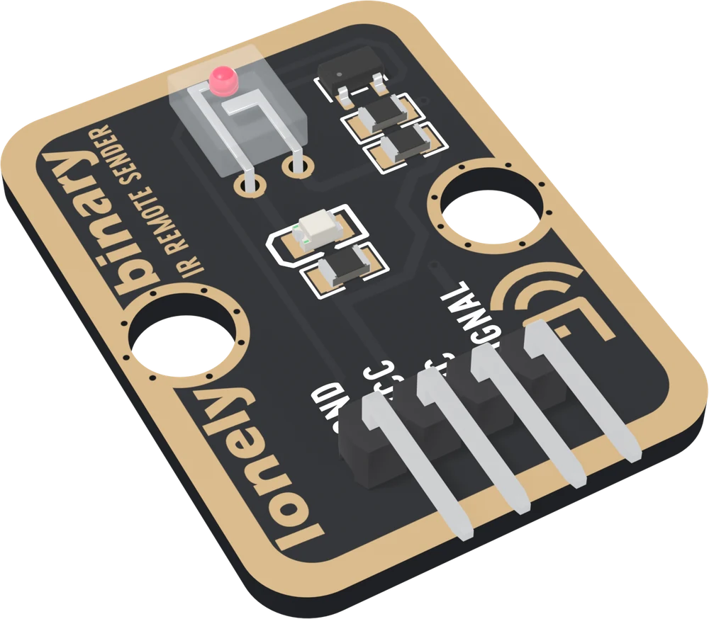
The LED is an Everlight IR908-7C, a sidelooker that shines out of one side of its clear package. It lies flat with that side facing up, so the beam leaves the parts side of the board. The beam is 40° in all, ±20° off axis, half the receiver's ±45°: the sender is the half you aim.
Where the current comes from
SIGNAL does not light the LED. It puts a couple of milliamps into the transistor's base through 1 kΩ, and the transistor lets VCC push current through the LED and its 150 Ω resistor:
| VCC | LED current | Reach |
|---|---|---|
| 3.3 V | about 13 mA | about three quarters of the 5 V case |
| 5 V | about 24 mA | the reference |
Reach follows the square root of current, so 5 V buys about a third more range than 3.3 V. Both currents are inside the LED's 50 mA rating. Keep VCC at 5 V or below: the resistor is the only limit.
Which pin is which
Parts up, header at the bottom, left to right:
| GND | to your board's GND | the square pad: count from here |
| VCC | to 5V, or 3V3 | feeds the LEDs only |
| NC | nothing | not connected on the board |
| SIGNAL | to a digital output | HIGH lights the LED |
SIGNAL is active HIGH, the opposite of the receiver, and IRremote's default, so nothing needs setting. The back prints TK16 IR REMOTE SENDER instead of pin names; the square pad, on the right from the back, is GND.
Wiring, in three lines
- GND to your board's GND.
- VCC to 5V (VBUS on a Pico) for range; 3V3 works.
- SIGNAL to a digital pin: D3 on an Uno, GPIO 22 on an ESP32, GPIO 6 on an ESP32-S3, GP17 on a Pico.
Leave NC unconnected.
Example
Sends one NEC code every two seconds. The address and command are placeholders: put in numbers you read off your own remote with the TK15 receiver, because there is no table to look them up in.
#include <IRremote.hpp>   // IRremote by shirriff, z3t0 and ArminJo

// Uno: 3. ESP32: 22. ESP32-S3: 6. Pico: 17.
const int IR_TX_PIN = 3;

const uint16_t ADDRESS = 0x04;   // REPLACE: from your own remote
const uint8_t COMMAND = 0x16;    // REPLACE: from your own remote

void setup() {
  Serial.begin(115200);
  IrSender.begin(IR_TX_PIN);
}

void loop() {
  Serial.flush();        // on an Uno, no interrupt mid-frame
  IrSender.sendNEC(ADDRESS, COMMAND, 0);   // 0 repeats: one press
  Serial.println("sent");
  delay(2000);
}# mpremote mip install "github:peterhinch/micropython_ir/ir_tx"
# Sending works on an ESP32 or a Pico; not on an ESP8266.
import time
from machine import Pin
from ir_tx.nec import NEC
# ESP32: 22. ESP32-S3: 6. Pico: 17.
IR_TX_PIN = 6
ADDRESS = 0x04 # REPLACE: from your own remote
COMMAND = 0x16 # REPLACE: from your own remote
nec = NEC(Pin(IR_TX_PIN, Pin.OUT, value=0)) # LOW: LED off
while True:
nec.transmit(ADDRESS, COMMAND)
print("sent")
time.sleep(2)Where to start
The TK16 shares its handbook with the receiver, because nothing you send is useful until you have read a code off a remote. It is shelved on the IR receiver's page. The two chapters about this board are the sender, pin by pin, the transistor and what the supply decides, and be the remote, which sends a code you captured.
When it doesn’t work
- Nothing happens, and the LED looks dead.
- It is invisible: 940 nm is outside what an eye responds to. Point a phone camera at the clear LED; most show it as a faint flicker. The red LED beside it is on the same transistor, so it lights whenever the infrared one does.
- Does sending take a timer, or fix which pin I can use?
- On an Uno IRremote makes the carrier in software on any pin and takes no timer. On an ESP32, ESP32-S3 or Pico it uses a hardware PWM channel by default, also on any pin. Receiving is what takes Timer2 on an Uno.
- Can a 3.3 V board drive it with VCC on 5 V?
- Yes, and it is the combination to use. The pin only supplies base current through 1 kΩ; the LED's 24 mA comes from the 5 V rail through the transistor. VCC never reaches SIGNAL.
- The receiver ignores what I send.
- Two usual causes. The protocol: send the one you decoded, sendNEC for an NEC remote. Or the boards are too close: within about 20 cm the receiver is swamped and the decode fails on a working link. Try 30 cm.
- How do I get more range?
- Move VCC from 3V3 to 5V: the 150 Ω resistor is fixed, so the current nearly doubles and the reach grows by about a third. Then aim it: ±20 degrees is narrow enough to miss with. Do not go above 5 V; nothing else limits the LED's current.