Specifications
| Type | 7-segment display with 74HC595 shift register |
|---|---|
| Interface | Three wires: data, clock, latch |
| Outputs | 8 per register, chainable |
| Supply voltage | 3.3 V or 5 V |
What it is
A shift register turns three pins into eight. You clock bits in one at a time, then pulse the latch and all eight outputs change at once.
The reason to learn it on a display is that the result is visible: get the bit order wrong and you see it immediately in which segments light. But the technique is general — the same chip drives relays, LEDs, anything that needs more outputs than the board has pins. Chain two and three pins drive sixteen outputs.
The latch is the part people skip. Without it the outputs change as the bits shift through, so the display flickers through garbage on every update. Latch after the last bit and the change is atomic.
shiftOut() does the clocking in one call, which is fine for a display and too
slow for anything that needs speed. SPI does the same thing in hardware.
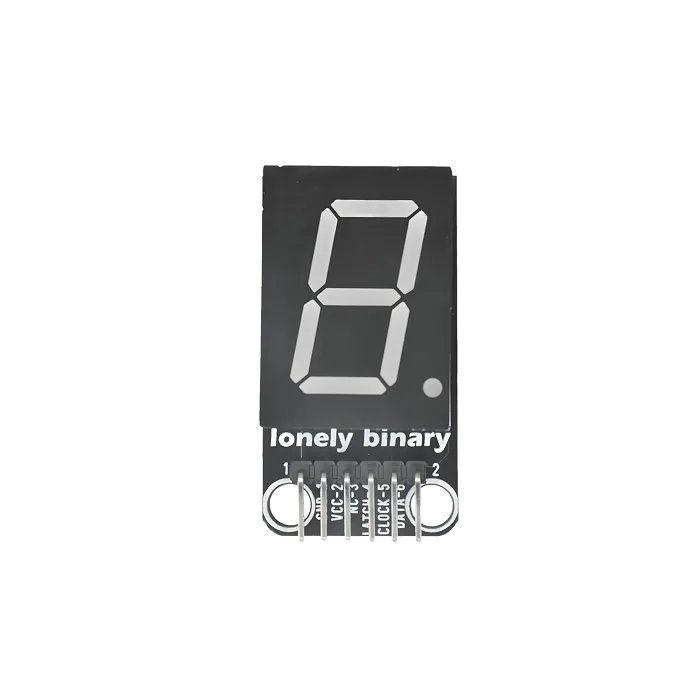
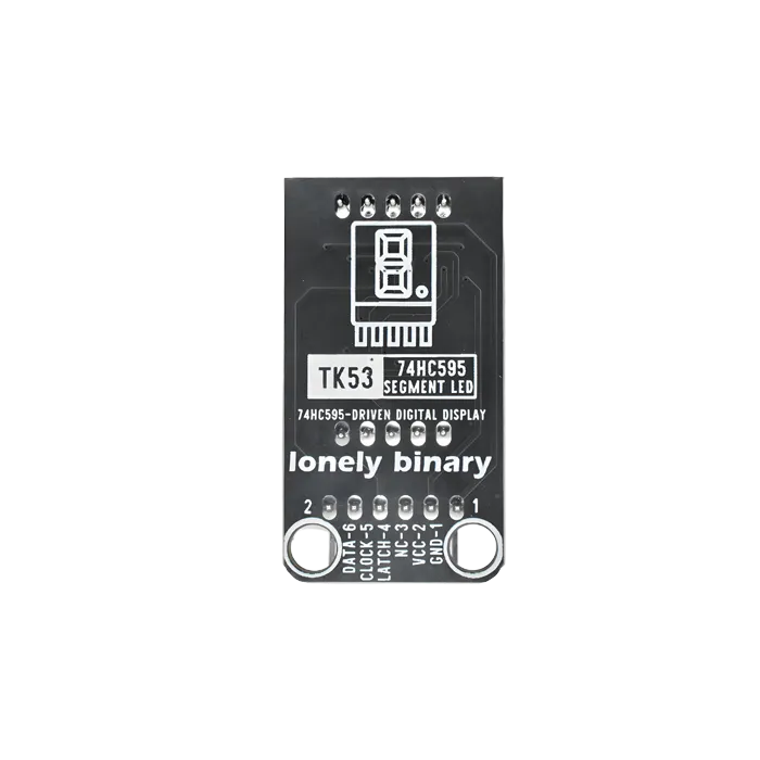
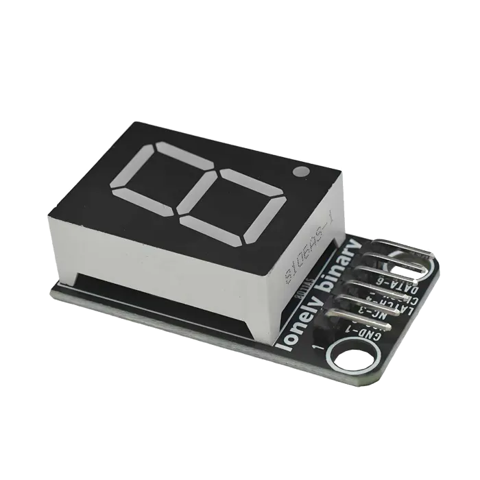
Pinout
- GND (negative): Like the negative terminal (-) of a battery, connect to the control board's GND
- VCC (positive): Like the positive terminal (+) of a battery, connect to the control board's 3.3V or 5V (this module supports both 3.3V and 5V)
- NC (no connection): No actual circuit connection, included for unified interface, can be left unconnected
- LATCH (latch): Data latch signal, connect to the control board's digital pin (e.g. Arduino D8 or Pico GPIO 2)
- CLOCK (clock): Shift clock signal, connect to the control board's digital pin (e.g. Arduino D12 or Pico GPIO 3)
- DATA (data): Serial data input, connect to the control board's digital pin (e.g. Arduino D11 or Pico GPIO 4)
Wiring
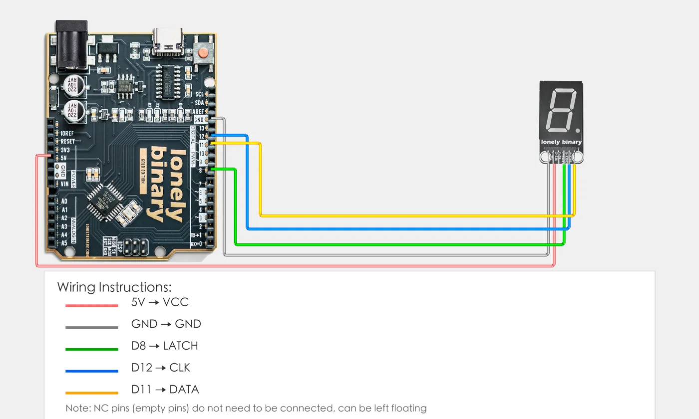
- GND → Control board GND
- VCC → Control board 3.3V or 5V
- LATCH → Control board digital pin (e.g. D8)
- CLOCK → Control board digital pin (e.g. D12)
- DATA → Control board digital pin (e.g. D11)
Example
// Pin number: change these to match your wiring
#define LATCH_PIN 8   // Arduino digital pin connected to LATCH (e.g. D8)
#define CLOCK_PIN 12  // Arduino digital pin connected to CLOCK (e.g. D12)
#define DATA_PIN 11   // Arduino digital pin connected to DATA (e.g. D11)

// 7-segment display segment code table (common anode, numbers 0-9)
byte digitPatterns[10] = {
  0b11111100,  // 0
  0b01100000,  // 1
  0b11011010,  // 2
  0b11110010,  // 3
  0b01100110,  // 4
  0b10110110,  // 5
  0b10111110,  // 6
  0b11100000,  // 7
  0b11111110,  // 8
  0b11110110   // 9
};

void setup() {
  // Initialize pin modes
  pinMode(LATCH_PIN, OUTPUT);
  pinMode(CLOCK_PIN, OUTPUT);
  pinMode(DATA_PIN, OUTPUT);

  // Start serial for debugging (9600 baud)
  Serial.begin(9600);

  Serial.println("74HC595 7-segment display program started");
  Serial.println("Cycling through 0-9");
}

void loop() {
  // Cycle through 0-9
  for (int i = 0; i < 10; i++) {
    displayDigit(i);
    Serial.print("Display number: ");
    Serial.println(i);
    delay(1000);  // Switch number every second
  }
}

// Display digit function
void displayDigit(int digit) {
  if (digit < 0 || digit > 9) return;  // Check range

  // Latch pin LOW, ready to receive data
  digitalWrite(LATCH_PIN, LOW);

  // Send data through shift register
  shiftOut(DATA_PIN, CLOCK_PIN, LSBFIRST, digitPatterns[digit]);

  // Latch pin HIGH, output data to display
  digitalWrite(LATCH_PIN, HIGH);
}from machine import Pin
import time
# Pin number: change these to match your wiring
LATCH_PIN = 0 # GPIO connected to LATCH (e.g. GPIO 0)
CLOCK_PIN = 1 # GPIO connected to CLOCK (e.g. GPIO 1)
DATA_PIN = 2 # GPIO connected to DATA (e.g. GPIO 2)
# 7-segment display segment code table (common anode, numbers 0-9)
digit_patterns = [
0b11111100, # 0
0b01100000, # 1
0b11011010, # 2
0b11110010, # 3
0b01100110, # 4
0b10110110, # 5
0b10111110, # 6
0b11100000, # 7
0b11111110, # 8
0b11110110 # 9
]
# Initialize pins
latch = Pin(LATCH_PIN, Pin.OUT)
clock = Pin(CLOCK_PIN, Pin.OUT)
data = Pin(DATA_PIN, Pin.OUT)
def display_digit(digit):
"""Display digit function"""
if digit < 0 or digit > 9:
return # Check range
# Latch pin LOW, ready to receive data
latch.value(0)
# Send data through shift register
shift_out(data, clock, digit_patterns[digit])
# Latch pin HIGH, output data to display
latch.value(1)
def shift_out(data_pin, clock_pin, value):
"""Shift output function (LSBFIRST, least significant bit first)"""
for i in range(8):
# Send least significant bit
data_pin.value(value & 0x01)
# Clock rising edge
clock_pin.value(1)
time.sleep_us(1)
clock_pin.value(0)
time.sleep_us(1)
# Shift right by one bit
value >>= 1
print("74HC595 7-segment display program started")
print("Cycling through 0-9")
# Main loop: runs forever
while True:
# Cycle through 0-9
for i in range(10):
display_digit(i)
print(f"Display number: {i}")
time.sleep(1) # Switch number every secondWhen it doesn’t work
- The segments light in the wrong order.
- Bit order. `shiftOut` takes MSBFIRST or LSBFIRST — try the other one before rewiring anything.
- The display flickers while updating.
- The latch pin is being pulsed too early, or not at all. Shift all eight bits first, then latch once.
- Only some segments ever light.
- Common-anode versus common-cathode. Invert the byte and see if it comes right.