Specifications
| Type | Digital temperature and humidity sensor on an I²C breakout board |
|---|---|
| Sensor | Sensirion SHT31-DIS, DFN-8, 2.5 × 2.5 mm, calibrated and linearised at the factory |
| Temperature | −40 to 125 °C specified, ±0.2 °C typical, 0.01 °C resolution |
| Humidity | 0 to 100 % RH specified, ±2 % RH typical, 0.01 % resolution |
| Recommended range | 5 to 60 °C and 20 to 80 % RH. Outside that, and especially above 80 % RH, the humidity reading temporarily offsets and recovers on its own |
| I²C address | 0x44 as shipped. Bridge the ADDR pads on the back for 0x45, which is the only other address the sensor has |
| Wires to your board | 4 — GND, VCC, SDA and SCL. The two signal wires are shared with every other I²C device on the project |
| Supply voltage | 3–5 V is what the board is printed; the sensor itself takes 2.15 to 5.5 V. Whatever you feed VCC is what the bus idles at, so 3V3 beside a 3.3 V board |
| Pull-up resistors | 2 × 10 kΩ, on SDA and SCL, already fitted and connected. Cut the I2C PULL-UP jumper on the back to disconnect both |
| Measurement time | 12.5 ms typical at high repeatability, 15 ms maximum; 2.5 ms at low. One reading is about 21 ms with Adafruit's library, almost all of it waiting |
| Current | 600 µA while measuring, 0.2 µA idle, 1.7 µA averaged at one reading a second. The power light adds about 270 µA at 3.3 V and cannot be switched off in software |
| Board | 23.2 × 31.2 mm, 4-pin 2.54 mm header, two 4.8 mm mounting holes, and a 1 mm slot routed round the sensor so the board conducts less heat to it |
| Not brought out | ALERT and nRESET. There is no interrupt output and no hardware reset; the soft reset command is the only reset |
| In the box | 1 × TK120 board. It also ships inside the TinkerBlock kits |
What it does
Temperature and relative humidity, both already calibrated, over the two wires every other I²C device on your project is using anyway.
The part doing the work is a Sensirion SHT31-DIS, 2.5 mm square, smaller than one of the header pads. Inside it are a capacitive humidity element, a temperature element, a converter for both, and a memory holding the calibration burned in at the factory — which the sensor reloads before every single measurement. Nothing on this board needs trimming, no reference voltage has to be supplied, and there is no curve to model.
The two jumpers on the back
This is the part of the board a spec table cannot tell you, and the part that decides whether two of these work together.
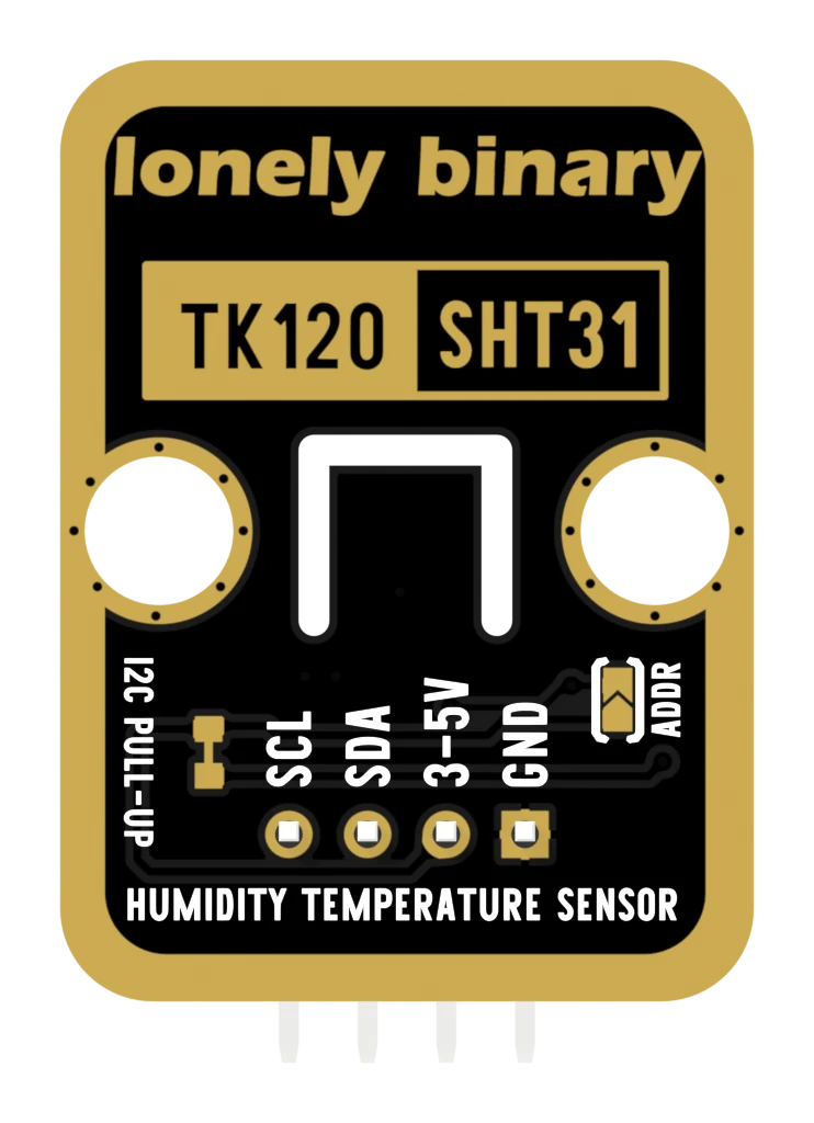
I2C PULL-UP is joined by a strip of copper a quarter of a millimetre wide. It is what connects R1 and R2 — the two 10 kΩ pull-ups on SDA and SCL — to VCC. Cut it and both come off the supply.
ADDR is open. Bridging its two pads with solder ties the sensor's address pin to VCC, and the board moves from 0x44 to 0x45.
They are the opposite way round to most boards, which is worth checking with your own eyes before you reach for a knife.
Which pin is which
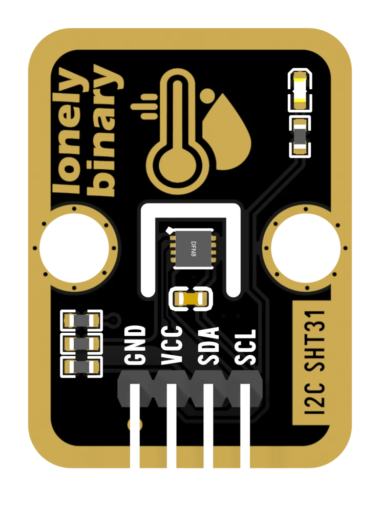
Sensor side up, header at the bottom, reading left to right:
| GND | ground | the square pad — count from here |
| VCC | 3V3, or 5V on an Uno | sets what the bus idles at |
| SDA | data | shared, pulled up on the board |
| SCL | clock | shared, pulled up on the board |
The back prints the same four names mirrored, which is the usual way to get SDA and SCL swapped. And swapping them is invisible: both lines still idle high, because both still have a resistor on them.
Wiring, in four lines
- GND to your board's GND. First, every time.
- VCC to 3V3 on an ESP32, ESP32-S3 or Pico; 5V on an Arduino Uno.
- SDA to your board's SDA — A4 on an Uno, GPIO 21 on an ESP32, GPIO 8 on an ESP32-S3, GP4 on a Pico.
- SCL to your board's SCL — A5, GPIO 22, GPIO 9, GP5.
Nothing else. The pull-ups are fitted, so there are no resistors to add.
Example
Install Adafruit SHT31 Library from the Library Manager, and accept Adafruit BusIO when it offers it.
#include <Adafruit_SHT31.h>

Adafruit_SHT31 sht;

void setup() {
  Serial.begin(115200);
  while (!Serial) delay(10);

  // 0x44 as shipped; 0x45 if the ADDR pads on the back are bridged.
  // begin() brings up Wire itself, on this board's default SDA and SCL.
  if (!sht.begin(0x44)) {
    Serial.println("no SHT31 at 0x44 - check GND first, then SDA and SCL");
    while (true) delay(100);
  }
}

void loop() {
  float celsius, humidity;

  // One measurement, both numbers. readTemperature() and readHumidity()
  // would take two — this library caches nothing at all.
  if (sht.readBoth(&celsius, &humidity)) {
    Serial.print(celsius);  Serial.print(" C  ");
    Serial.print(humidity); Serial.println(" %");
  } else {
    Serial.println("read failed");   // a checksum did not match
  }

  delay(2000);
}from machine import I2C, Pin
import time
# 0x2400: measure once, high repeatability, no clock stretching.
ADDR = 0x44
i2c = I2C(0, sda=Pin(8), scl=Pin(9), freq=100_000)
def crc8(data):
crc = 0xFF
for b in data:
crc ^= b
for _ in range(8):
crc = ((crc << 1) ^ 0x31) & 0xFF if crc & 0x80 else (crc << 1) & 0xFF
return crc
def read():
i2c.writeto(ADDR, b"\x24\x00")
time.sleep_ms(20) # 15 ms is the datasheet maximum
d = i2c.readfrom(ADDR, 6) # temperature first, then humidity
if d[2] != crc8(d[0:2]) or d[5] != crc8(d[3:5]):
return None # a byte did not survive the wires
t = -45 + 175 * ((d[0] << 8) | d[1]) / 65535
rh = 100 * ((d[3] << 8) | d[4]) / 65535
return t, rh
while True:
r = read()
print("%.2f C %.2f %%" % r if r else "read failed")
time.sleep(2)Where to start
The handbook below is eleven short articles with a working figure in each. If you want a reading now, the first reading is the whole build in one sketch.
If you only read one, read the two jumpers — it is the only thing about this board you cannot work out by looking at it, and it decides whether a second one of these will work.
And if the temperature reads high, the slot round the sensor explains what the board already does about that and what is left for you.
Wiring diagram
Full board reference: ESP32-S3 pinout.
When it doesn’t work
- Nothing shows up on an I²C scan.
- Check GND first: without it the sensor has no reference, and the power light can still glow by borrowing a return path through the signal lines. Then check that SDA and SCL are not swapped — both lines still idle high when they are, because both carry a pull-up, so the board looks perfectly normal. Then check VCC is on a rail that is actually powered.
- Which address is it, 0x44 or 0x45?
- 0x44 out of the bag. R3 on the board holds the sensor's ADDR pin at ground, which is what fixes it there — the datasheet is explicit that ADDR must never be left floating. Bridging the ADDR pads on the back ties ADDR to VCC instead and the board becomes 0x45. There is no third address.
- Can I put two of these on one bus?
- Two, and no more. Bridge the ADDR pads on one of them so they are 0x44 and 0x45. Leave both jumpers open and both boards answer at 0x44 at the same time — a scanner then reports one device where there are two, which is why this failure is so hard to spot.
- Should I cut the I2C PULL-UP jumper on the second board?
- Usually not. Two 10 kΩ pull-ups in parallel are 5 kΩ, and that makes the bus faster rather than slower: a lower resistance pulls the lines back up sooner. Cut them only when several devices each bring their own and the total is getting under about 2 kΩ.
- It reads a degree or two above my room thermometer.
- The sensor is measuring its own surroundings, and its surroundings are your project. The 1 mm slot routed round it stops the board conducting heat up to it, which is most of what a board can do about the problem — the rest is placement. Get it out of the breadboard on four long wires, away from regulators and displays.
- Can I power it from 5V next to an ESP32?
- No. The board's pull-ups tie SDA and SCL to whatever is on VCC, so a 5 V supply idles both signal lines at 5 V against pins rated for 3.3 V. It appears to work, which is the problem. The sensor is specified from 2.15 V, so 3V3 costs you nothing.
- Every reading comes back as a failed read or NaN.
- The sensor is answering and its six bytes are not surviving the wires — each pair carries a CRC-8, and the library throws the whole reading away if either fails rather than printing a number that is wrong by tens of degrees. Shorten the jumpers, come off the breadboard, and put the clock back to 100 kHz if you raised it. An occasional failure is normal and worth retrying.
- Is the SHT31 worth it over the DHT22 in the same kit?
- For humidity, they are both ±2 % and there is little to choose. For temperature the SHT31 is ±0.2 °C against the DHT22's ±0.5, it reports in hundredths, it checksums every reading, and it shares two wires instead of taking a pin of its own. If you want more than two sensors on one project, that last point is the whole argument.