Specifications
| Type | LM75 digital temperature sensor |
|---|---|
| Interface | I2C, address 0x48–0x4F |
| Range | -55 to +125 °C |
| Accuracy | ±2 °C typical |
| Resolution | 0.5 °C, 9-bit |
| Supply voltage | 3.3 V or 5 V |
What it is
A temperature sensor with the conversion already done inside it. Read two bytes over I2C and you have degrees.
Set against TK12, the thermistor: this costs more and gives up response speed, and in exchange you get a number that means the same thing on every board with no calibration, no divider maths and no drift. For anything that will be read by someone other than you, that trade is almost always right.
Three address pins let up to eight of them share one bus, which is how you instrument several points in an enclosure with two wires.
It also has an interrupt output that trips above a temperature you program — useful for a thermal cut-off that works even if the code hangs.
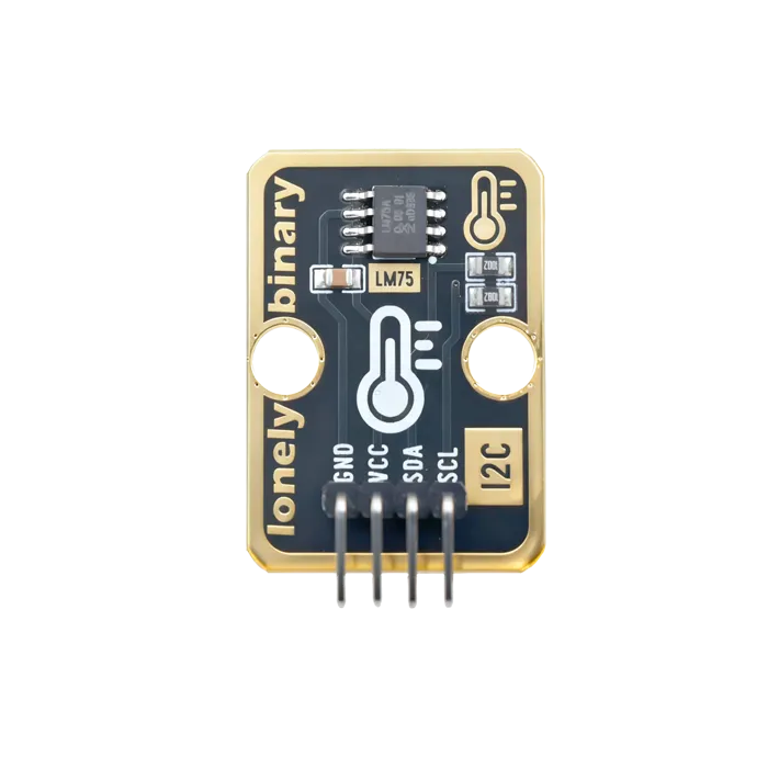
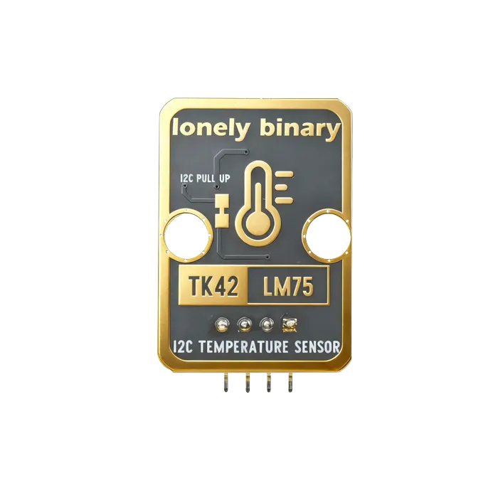
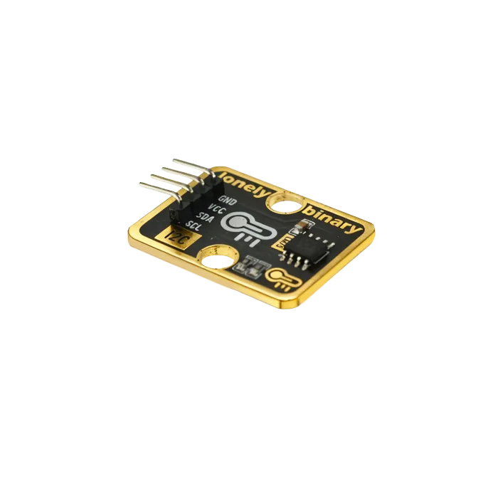
Pinout
- GND (negative): Like the negative terminal (-) of a battery, connect to the control board's GND
- VCC (positive): Like the positive terminal (+) of a battery, connect to the control board's 3.3V or 5V (this module supports both 3.3V and 5V)
- SDA (data line): I2C data line, connect to the control board's SDA pin (Arduino Uno A4 or Pico GPIO 0)
- SCL (clock line): I2C clock line, connect to the control board's SCL pin (Arduino Uno A5 or Pico GPIO 1)
Wiring
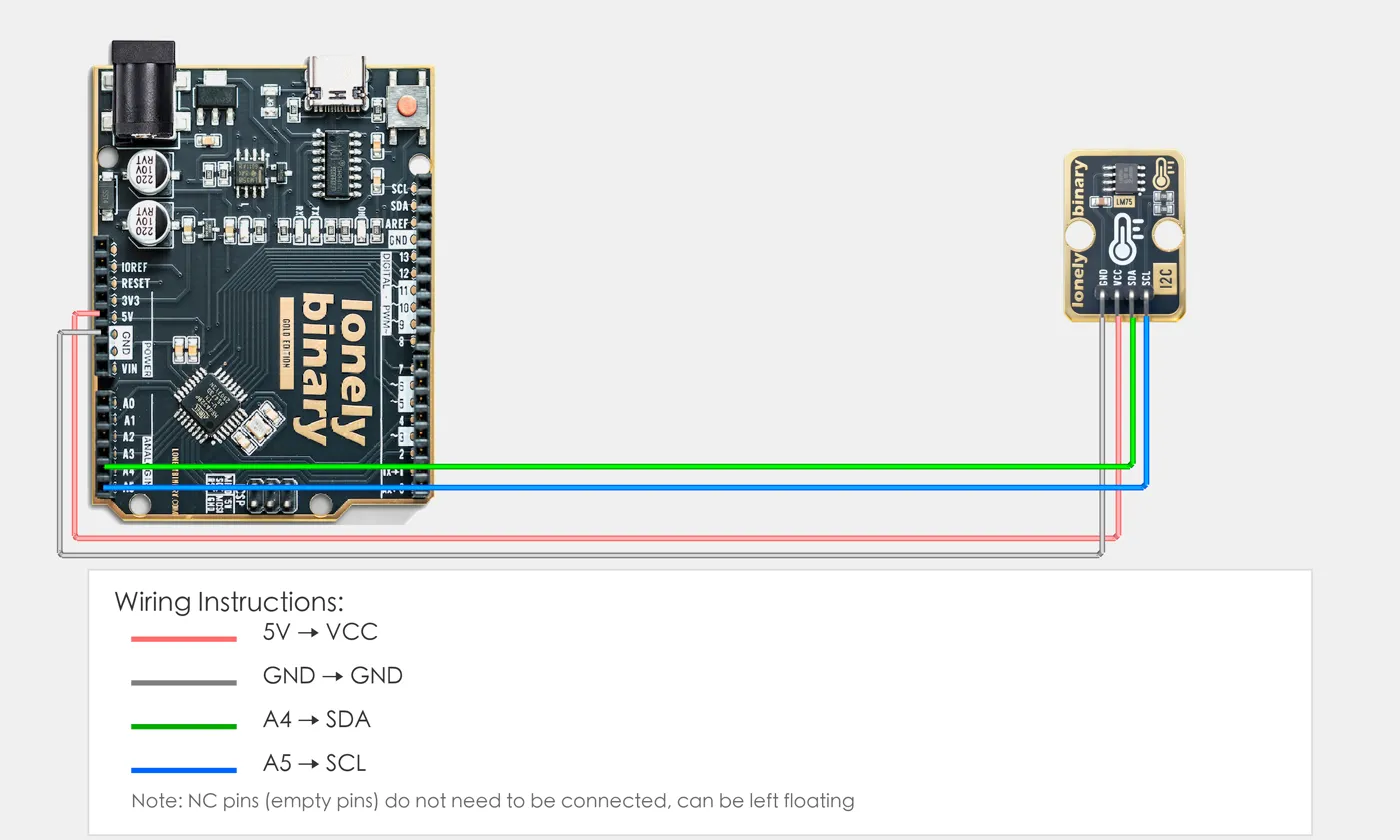
- GND → Control board GND
- VCC → Control board 3.3V or 5V
- SDA → Control board SDA pin
- SCL → Control board SCL pin
Example
// Include Wire library for I2C communication
// Arduino Uno R3 I2C pins are fixed: SDA=A4, SCL=A5
#include <Wire.h>

// LM75 I2C address (usually 0x48)
#define LM75_ADDRESS 0x48

void setup() {
  // Start I2C communication
  Wire.begin();

  // Start serial for debugging (9600 baud)
  Serial.begin(9600);
}

void loop() {
  // Read temperature value
  Wire.beginTransmission(LM75_ADDRESS);
  Wire.write(0x00);  // Temperature register address
  Wire.endTransmission();

  // Read 2 bytes of data
  Wire.requestFrom(LM75_ADDRESS, 2);
  if(Wire.available() >= 2) {
    int highByte = Wire.read();      // High byte
    int lowByte = Wire.read();        // Low byte

    // Combine into 16-bit temperature value
    int tempRaw = (highByte << 8) | lowByte;

    // Convert to actual temperature (unit: Celsius)
    // LM75 temperature value is 11-bit, highest bit is sign bit
    float temperature = (tempRaw >> 5) * 0.125;

    // Display temperature on Serial Monitor
    Serial.print("Temperature: ");
    Serial.print(temperature);
    Serial.println("°C");
  }

  // Delay 1 second to avoid reading too fast
  delay(1000);
}# Import required modules
from machine import Pin, I2C # GPIO control and I2C communication
import time # For delay (time.sleep)
# Define I2C address and pins
LM75_ADDRESS = 0x48 # LM75 I2C address (usually 0x48)
SDA_PIN = 0 # GPIO connected to SDA (e.g. GPIO 0)
SCL_PIN = 1 # GPIO connected to SCL (e.g. GPIO 1)
# Create I2C object
i2c = I2C(0, sda=Pin(SDA_PIN), scl=Pin(SCL_PIN), freq=100000) # Create I2C object, frequency 100kHz
# Main loop: runs forever
while True:
# Read temperature value (read 2 bytes from register 0x00)
data = i2c.readfrom_mem(LM75_ADDRESS, 0x00, 2) # Read 2 bytes from address 0x00
# LM75 returned data: data[0] is high byte (MSB), data[1] is low byte (LSB)
# Combine into 16-bit temperature value (high byte first, big-endian)
tempRaw = (data[0] << 8) | data[1]
# Convert to actual temperature (unit: Celsius)
# LM75 temperature value is 11-bit signed number, unit is 0.125°C
# Method: Keep consistent with Arduino version, directly shift right by 5 bits
# Note: Python's right shift for signed numbers performs sign extension
# First convert unsigned number to signed number (if highest bit is 1)
if tempRaw & 0x8000:
tempRaw_signed = tempRaw - 0x10000
else:
tempRaw_signed = tempRaw
# Shift right by 5 bits to get 11-bit temperature value, then multiply by 0.125
temperature = (tempRaw_signed >> 5) * 0.125
# Display temperature on terminal
print("Temperature: {:.2f}°C".format(temperature))
# Delay 1 second to avoid reading too fast
time.sleep(1)When it doesn’t work
- The bus scan finds nothing.
- Check pull-ups. Most breakouts have them, but several modules on one bus can over-load it. 4.7 kΩ once, not once per module.
- Two sensors report the same value.
- They are at the same address. Strap A0–A2 differently on each; the address is 0x48 plus those three bits.
- The reading is a degree or two above room temperature.
- Self-heating and board heat. It is measuring its own PCB. Move it away from the regulator, or accept the offset and subtract it.