Specifications
| Type | Active buzzer with internal oscillator |
|---|---|
| Frequency | Fixed, about 2 kHz |
| Control | Digital high/low |
| Supply voltage | 3.3 V or 5 V |
What it is
A piezo element with an oscillator built into the package. Give it power and it makes its one note; take the power away and it stops.
That single fixed pitch is the difference from TK37, and it is the reason to
choose this one. For an alarm, a keypress confirmation or a "something is wrong"
beep you do not want a melody — you want one line of code and a noise. It also
frees the timer that tone() would otherwise claim.
It is loud. Louder than you expect on a desk at two in the morning, and there is no volume control: PWM changes the duty cycle, not the amplitude, and mostly just makes it sound worse. If you need it quieter, put tape over the hole — which sounds like a joke and is what everyone actually does.
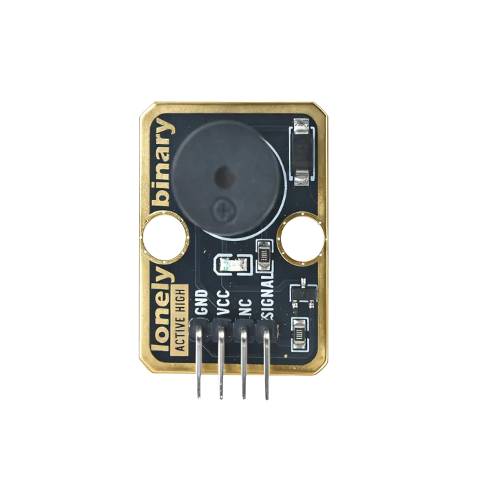
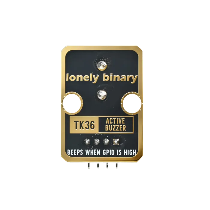
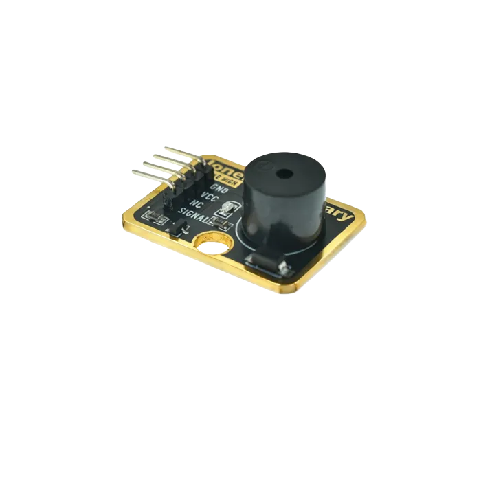
Pinout
- GND (negative): Like the negative terminal (-) of a battery, connect to the control board's GND
- VCC (positive): Like the positive terminal (+) of a battery, connect to the control board's 3.3V or 5V (this module supports both 3.3V and 5V)
- NC (no connection): No actual circuit connection, included for unified interface, can be left unconnected
- SIGNAL (signal input): Pin to control buzzer, connect to the control board's digital pin (e.g. Arduino D3 or Pico GPIO 0)
- When HIGH (HIGH/1) is input, buzzer emits sound
- When LOW (LOW/0) is input, buzzer stops
- Can only emit fixed frequency sound, cannot change pitch
Wiring
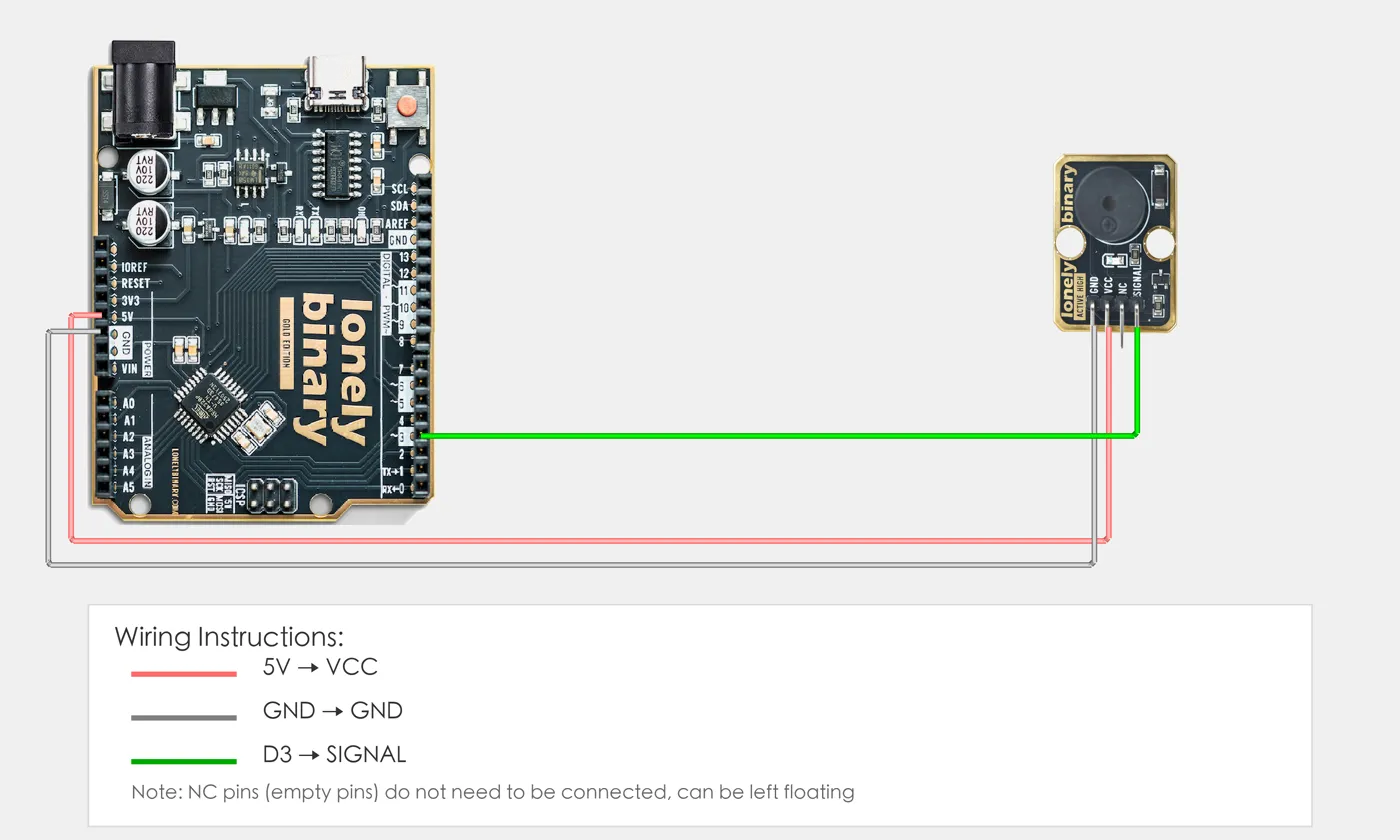
- GND → Control board GND
- VCC → Control board 3.3V or 5V
- SIGNAL → Control board digital pin (use the pin defined in your program)
Example
// Pin number: change this to match your wiring
#define BUZZER_PIN 3  // Arduino digital pin connected to SIGNAL (e.g. D3)

void setup() {
  // Initialize pin mode
  pinMode(BUZZER_PIN, OUTPUT);

  // Start serial for debugging (9600 baud)
  Serial.begin(9600);

  Serial.println("Active buzzer program started");
}

void loop() {
  // Buzzer on for 0.5 seconds
  digitalWrite(BUZZER_PIN, HIGH);  // Turn on buzzer
  Serial.println("Buzzer on");
  delay(500);  // Wait 0.5 seconds

  // Buzzer off for 0.5 seconds
  digitalWrite(BUZZER_PIN, LOW);   // Turn off buzzer
  Serial.println("Buzzer off");
  delay(500);  // Wait 0.5 seconds
}# Import required modules
from machine import Pin # GPIO control
import time # For delay (time.sleep)
# Pin number: change this to match your wiring
BUZZER_PIN = 0 # GPIO connected to SIGNAL (e.g. GPIO 0)
# Create Pin object, set as output mode
buzzer = Pin(BUZZER_PIN, Pin.OUT)
print("Active buzzer program started")
# Main loop: runs forever
while True:
# Buzzer on for 0.5 seconds
buzzer.on() # Turn on buzzer
print("Buzzer on")
time.sleep(0.5) # Wait 0.5 seconds
# Buzzer off for 0.5 seconds
buzzer.off() # Turn off buzzer
print("Buzzer off")
time.sleep(0.5) # Wait 0.5 secondsWhen it doesn’t work
- It is always on.
- Active buzzers sound whenever the pin is high. If it screams at boot, the pin is floating or the bootloader is holding it — pick a different pin or set it LOW first thing in `setup()`.
- PWM does not change the volume.
- It cannot. The oscillator is internal, so duty cycle just chops the sound. Use a passive buzzer with a series resistor if you need it quieter.
- I want it to play a tune.
- Wrong part — this one has a fixed pitch. TK37 is the passive buzzer and it takes `tone()`.