Specifications
| Chip | Texas Instruments INA219AIDCNR in a SOT-23-8 package — the A grade, so ±0.5% on the current reading at room temperature and ±1% over −25 to 85 °C |
|---|---|
| Shunt | 100 mΩ, 1%, rated 2 W. Yageo PT2512FK-7W0R1L, in the positive wire between the POWER terminal and the LOAD terminal |
| Current range | ±0.4, ±0.8, ±1.6 or ±3.2 A, chosen in software by the chip's gain setting. Above the setting you picked the reading sits at full scale and stops moving |
| Resolution | One count is 0.1 mA — 10 µV of shunt voltage across 100 mΩ. The fixed zero-point error is larger than that: up to ±1 mA on the narrowest setting and ±2 mA on the widest |
| Bus voltage | 0 to 26 V, measured from the LOAD + screw down to the board's ground. 26 V is an absolute maximum on the chip, not a recommendation |
| Supply | 3 to 5.5 V on the hole marked 3V3 — the chip's own supply, separate from the rail being measured. Feed it the same rail your microcontroller's logic runs at |
| Header | 4 pins on 2.54 mm pitch, right-angle, printed GND, 3V3, SCL, SDA. Note that SCL comes before SDA on this board |
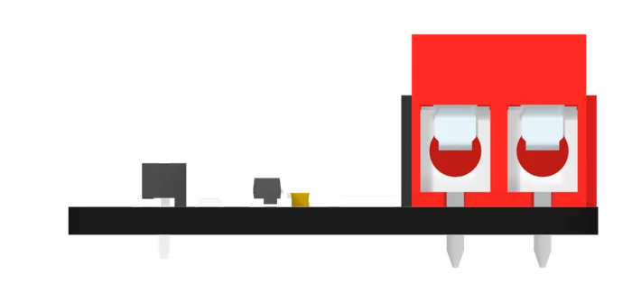
| Terminals | 2 KF301-5.0 screw terminals on 5 mm pitch: a red one marked POWER and a black one marked LOAD, each with a + and a − screw |
| Isolation | None. Both − screws, the GND pin and the chip's ground are one net, so the supply you are measuring has to share a ground with the board reading it |
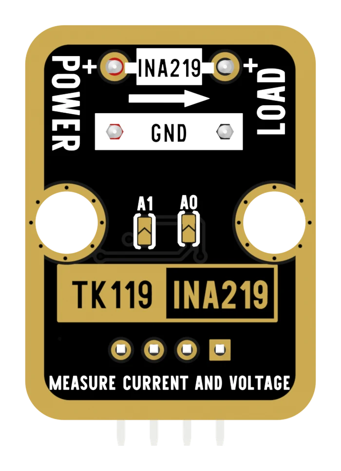
| I²C address | 0x40 out of the box. Two solder pads on the back, A1 and A0, give 0x40, 0x41, 0x44 and 0x45 — A1 is worth four and A0 is worth one |
| Pull-ups | 10 kΩ on SDA and on SCL, to the 3V3 rail. Fitted, and not removable — so this board sets the bus levels for anything sharing them |
| Power LED | Red, from the 3V3 rail through 5.1 kΩ — roughly 0.3 mA. On whenever the board has power, and on no GPIO |
| Size | 22.4 × 30.4 mm, two mounting holes |
What it is
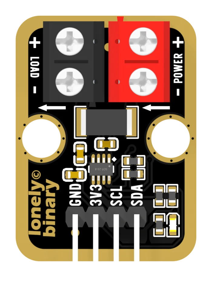
A resistor and a chip that reads it. The resistor — 100 milliohms, the large rectangular part between the two screw terminals — sits in the positive wire between your supply and your load, so everything the load draws goes through it. At 500 mA that makes 50 millivolts across it, and the INA219 beside it measures exactly that.
The same chip also measures the voltage on the load side of the resistor, and divides and multiplies to give you current in amps and power in watts. Only the two voltages are measurements; the other two are arithmetic, and one of the numbers in that arithmetic is a resistance your sketch has to tell it about.
Pinout
- GND (negative): Connect to the controller board's GND (like the negative terminal of a battery). This is the same net as both − screws on the terminals.
- 3V3 (positive): The chip's own supply, 3 to 5.5 V despite the label. Use the same rail your controller's logic runs at — the board's pull-up resistors pull the bus to whatever you put here.
- SCL (clock line): I²C clock, to the controller's SCL pin (Arduino Uno A5 or Pico GPIO 1). Third pin, not fourth.
- SDA (data line): I²C data, to the controller's SDA pin (Arduino Uno A4 or Pico GPIO 0).
The two screw terminals are the rail being measured, and they are not part of the header:
- POWER + and POWER −: the supply. The red terminal.
- LOAD + and LOAD −: the thing drawing the current. The black terminal.
The arrows printed between them point from POWER to LOAD, which is the direction the current has to flow for the reading to come out positive.
Wiring
- GND → controller board GND
- 3V3 → controller board 3.3 V or 5 V, matching its logic
- SCL → controller board SCL
- SDA → controller board SDA
- Supply + and − → POWER + and POWER −
- Load + and − → LOAD + and LOAD −
Connect the rail last, so nothing is live while a screwdriver is in the terminals.
Example
// TK119 INA219 wiring
//
//   TK119 GND  -> Arduino GND
//   TK119 3V3  -> Arduino 5V (an Uno's logic is 5 V, so the bus is 5 V)
//   TK119 SCL  -> Arduino A5     (third pin on the board)
//   TK119 SDA  -> Arduino A4     (fourth pin)
//   POWER + / - -> the supply you want to measure
//   LOAD  + / - -> the load
//
// Arduino IDE: Sketch > Include Library > Manage Libraries, then install
// "Adafruit INA219". No board-specific Tools settings.

#include <Wire.h>
#include <Adafruit_INA219.h>

// 0x40 with nothing soldered. 0x41, 0x44 or 0x45 if you bridged A0 or A1.
Adafruit_INA219 ina219(0x40);

void setup() {
  Serial.begin(9600);
  if (!ina219.begin()) {
    Serial.println("no INA219 at 0x40 - check SCL and SDA, they are the other way round here");
    while (1) delay(10);
  }
  // The library's default is the 32 V, 2 A calibration. Say which range you
  // want: the narrower ones are more accurate, not merely smaller.
  ina219.setCalibration_32V_2A();
  Serial.println("bus V\tshunt mV\tcurrent mA\tpower mW");
}

void loop() {
  float bus   = ina219.getBusVoltage_V();     // measured, at the LOAD + screw
  float shunt = ina219.getShuntVoltage_mV();  // measured, across the resistor
  float mA    = ina219.getCurrent_mA();       // shunt voltage / 0.1 ohm
  float mW    = ina219.getPower_mW();         // from the chip's power register

  Serial.print(bus, 3);   Serial.print('\t');
  Serial.print(shunt, 2); Serial.print('\t');
  Serial.print(mA, 1);    Serial.print('\t');
  Serial.println(mW, 1);
  delay(500);
}# TK119 INA219 wiring
#
# TK119 GND -> Pico GND
# TK119 3V3 -> Pico 3V3
# TK119 SCL -> Pico GPIO 1 (third pin on the board)
# TK119 SDA -> Pico GPIO 0 (fourth pin)
# POWER + / - -> the supply you want to measure
# LOAD + / - -> the load
#
# No driver library needed: three registers is less code than installing one.
from machine import I2C, Pin
import time, struct
ADDR = 0x40 # 0x41, 0x44 or 0x45 if you bridged A0 or A1
SHUNT_OHMS = 0.1 # the resistor fitted on this board
i2c = I2C(0, scl=Pin(1), sda=Pin(0), freq=100_000)
# Config register: 32 V bus range, gain /8 (+-320 mV), 12-bit, continuous.
i2c.writeto_mem(ADDR, 0x00, struct.pack(">H", 0x399F))
def signed(v):
return v - 65536 if v & 0x8000 else v
while True:
shunt_raw = signed(struct.unpack(">H", i2c.readfrom_mem(ADDR, 0x01, 2))[0])
bus_raw = struct.unpack(">H", i2c.readfrom_mem(ADDR, 0x02, 2))[0]
shunt_mv = shunt_raw * 0.01 # one count is 10 uV
bus_v = (bus_raw >> 3) * 0.004 # three flag bits, then 4 mV per count
amps = shunt_mv / 1000 / SHUNT_OHMS
print("{:.3f} V {:.2f} mV {:.1f} mA {:.0f} mW".format(
bus_v, shunt_mv, amps * 1000, bus_v * amps * 1000))
time.sleep(0.5)Where to start
This block shares a handbook with the triple-channel INA3221, because the question a reader brings to either — how much current can it see, and how wrong is the number — is answered by comparing them. It is shelved on the set's page, and it starts with what a shunt measures.
The two chapters most about this block are the range you actually have, which is the four gain settings and what each one costs, and read one rail on an ESP32, which is this wiring done wire by wire with a sketch that prints all four numbers.
When it doesn’t work
- My current reading is negative.
- The supply and the load are in the wrong terminals. Current is meant to flow POWER → LOAD, which is the direction the two arrows printed between them point. Swap the two pairs of wires and the sign comes right. Nothing is damaged either way round, but with them swapped the voltage the board reports is the supply's rather than the load's.
- A scan finds nothing at 0x40.
- Almost always SCL and SDA. This board prints GND, 3V3, SCL, SDA — the clock before the data, which is the opposite of the other I²C blocks and of the INA3221 sold beside it. Check the silkscreen rather than the wire colours, then check that the red power LED is lit.
- The voltage looks right but the current is out by a factor of two.
- The chip does not measure current. It measures millivolts and divides by a resistance your sketch told it about, so a wrong shunt value or a wrong calibration number scales the current by exactly that ratio while leaving the voltage perfect. Set 0.1 Ω and the maximum current you expect, and nothing else.
- Can it measure my board's sleep current?
- No. One count is 0.1 mA and the zero-point error is worth about ±1 mA, while a sleeping ESP32 draws tens of microamps. This board shows you a rail at work — a Wi-Fi transmit burst, a motor starting, an LED strip at full brightness. Sleep current needs a meter with a microamp range.
- Can I put two of these on one bus?
- Up to four. The two pads on the back are A1 and A0, and bridging one joins that pin to the supply against a 10 kΩ pull-down. A1 is worth four and A0 is worth one, so the four addresses are 0x40, 0x41, 0x44 and 0x45 rather than four in a row. Write the address on the board with a marker once you have soldered it.
- How much current can it actually take?
- The chip stops reporting above 3.2 A, which is the limit that matters. The resistor is rated 2 W and dissipates about 1 W at 3.2 A, so it will be hot to the touch at the top of the range and is past its rating a little over 4 A. A 5 mm screw terminal of this size is normally rated for several times that, so neither the terminals nor the resistor is the limit you meet first.