Specifications
| Type | Reflective optical sensor (IR emitter and phototransistor) |
|---|---|
| Range | A few millimetres to about 2 cm |
| Output | Digital threshold, and analog on some variants |
| Supply voltage | 3.3 V or 5 V |
What it is
An infrared LED and a phototransistor pointing the same way. Something reflective in front sends light back; something dark or distant does not.
It measures reflectance, not distance, and conflating the two is the usual mistake. A white surface 2 cm away and a grey one at 1 cm can read identically. For line following that is fine — you only need to tell the line from the background — and for measuring a gap it is useless.
Range is short by design, a couple of centimetres at most, because reflected light falls off fast. Mount it close and shield it: ambient light, especially sunlight, adds a signal that has nothing to do with your surface.
Calibrate against the actual materials. Read the line, read the background, and put the threshold between them.
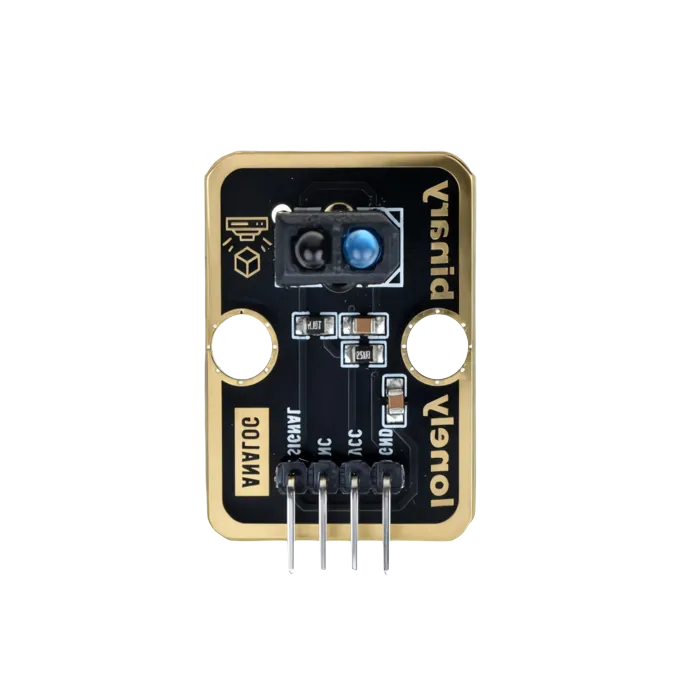
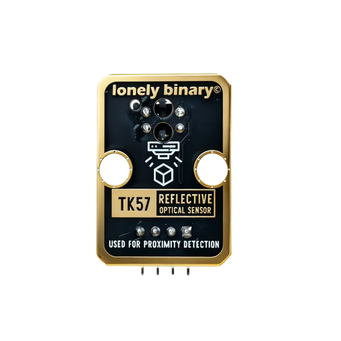
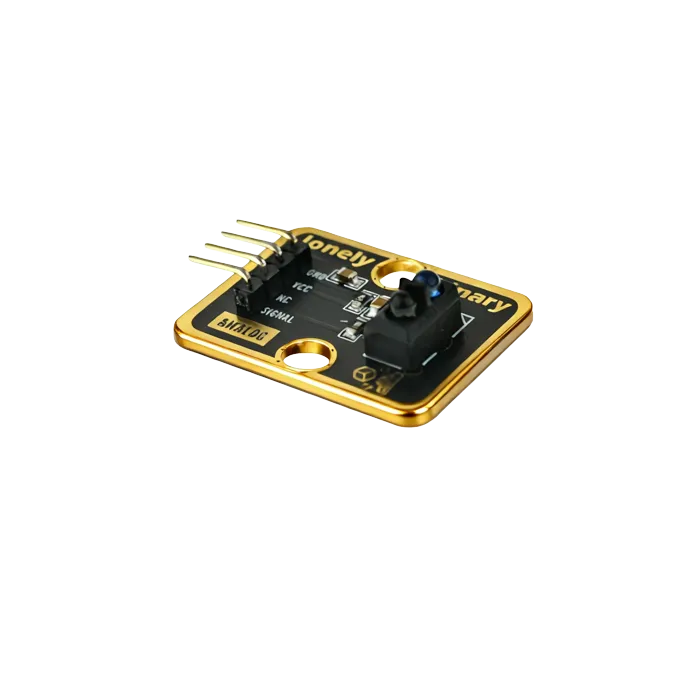
Pinout
- GND (negative): Like the negative terminal (-) of a battery, connect to the control board's GND
- VCC (positive): Like the positive terminal (+) of a battery, connect to the control board's 3.3V or 5V (this module supports both 3.3V and 5V)
- NC (no connection): No actual circuit connection, included for unified interface, can be left unconnected
- SIGNAL (signal output): Line tracking detection output pin, connect to the control board's digital pin (e.g. Arduino D2 or Pico GPIO 0)
- Outputs HIGH (HIGH/1) when black line is detected
- Outputs LOW (LOW/0) when white line is detected (or no black line detected)
Wiring
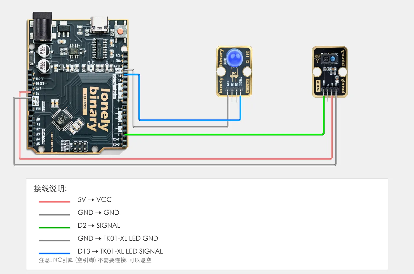
- GND → Control board GND
- VCC → Control board 3.3V or 5V
- SIGNAL → Control board digital pin (use the pin defined in your program)
Example
// Pin number: change this to match your wiring
#define TRACKER_PIN 2  // Arduino digital pin connected to SIGNAL (e.g. D2)
#define LED_PIN 13     // LED pin (Arduino built-in LED on pin 13, or external LED)

void setup() {
  // Initialize pin modes
  pinMode(TRACKER_PIN, INPUT);  // Set line tracker pin as input (to read detection state)
  pinMode(LED_PIN, OUTPUT);     // Set LED pin as output (to control LED on/off)

  // Start serial for debugging (9600 baud)
  Serial.begin(9600);

  Serial.println("Line tracker program started");
  Serial.println("LED on when black line detected, LED off when white line detected");
}

void loop() {
  // Read line tracker state
  int trackerState = digitalRead(TRACKER_PIN);  // Read sensor pin level: HIGH(1)=black line detected, LOW(0)=white line detected

  // Control LED based on detection state
  if (trackerState == HIGH) {
    // Black line detected: LED on
    digitalWrite(LED_PIN, HIGH);
    Serial.println("Black line detected - LED on");
  } else {
    // White line detected: LED off
    digitalWrite(LED_PIN, LOW);
    Serial.println("White line detected - LED off");
  }

  delay(100);  // Brief delay to avoid reading too fast
}# Import required modules
from machine import Pin # GPIO control
import time # For delay (time.sleep)
# Pin number: change these to match your wiring
TRACKER_PIN = 0 # GPIO connected to SIGNAL (e.g. GPIO 0)
LED_PIN = 1 # LED pin (GPIO 1, or external LED, Pico built-in LED is GPIO 25)
# Create pin objects
tracker = Pin(TRACKER_PIN, Pin.IN) # Set line tracker pin as input (to read detection state)
led = Pin(LED_PIN, Pin.OUT) # Set LED pin as output (to control LED on/off)
print("Line tracker program started")
print("LED on when black line detected, LED off when white line detected")
# Main loop: runs forever
while True:
# Read line tracker state
trackerState = tracker.value() # Read sensor pin level: 1=black line detected (HIGH), 0=white line detected (LOW)
# Control LED based on detection state
if trackerState == 1:
# Black line detected: turn LED on and print message
led.on() # Output HIGH, LED on
print("Black line detected - LED on")
else:
# White line detected: turn LED off
led.off() # Output LOW, LED off
print("White line detected - LED off")
# Delay 100 milliseconds to avoid reading too fast
time.sleep_ms(100)When it doesn’t work
- It reads the same over the line and off it.
- Not enough contrast in infrared. Some inks that look black to you reflect IR. Test with the real surface and try matte black tape.
- It works indoors, not near a window.
- Sunlight is full of IR. Shield the sensor, get it closer to the surface, or switch to a modulated sensor.
- Can I measure distance with it?
- Not reliably — reflectance and distance are confounded. Use TK50 for distance.