Specifications
| Type | Omnipolar Hall effect switch, active low: a magnet reads LOW, no magnet reads HIGH |
|---|---|
| Sensor | CrossChip CC6201 in TSOT-23-3, at the top left of the board. Micropower, non-latching |
| Threshold | Switches LOW at 40 G of either pole, back HIGH below 32 G (typical values, 8 G of hysteresis) |
| Response | Looks at the field once every 22 ms (typical), so SIGNAL changes up to 22 ms late and a magnet in range for less than that can be missed |
| Output | Push-pull, with a 10 kΩ pull-up to VCC on the board. No magnet, SIGNAL is at VCC; a magnet, near 0 V |
| Indicator | Red LED with a 1 kΩ resistor from VCC to SIGNAL. Lights while a magnet is near, about 3 mA from 5 V |
| Supply | 3.3 V or 5 V on VCC (the chip runs from 2 to 5 V, 5.5 V absolute maximum). SIGNAL sits at VCC with no magnet, so use 3V3 beside an ESP32, ESP32-S3 or Pico and 5V beside an Uno |
| Current | About 5 µA average with no magnet; about 3.5 mA from 5 V while a magnet holds the LED on |
| Pins to wire | 3 of the 4: GND, VCC and SIGNAL. NC is connected to nothing on the board |
| Header | 4-pin right-angle male, 2.54 mm pitch: GND, VCC, NC, SIGNAL, with GND on the square pad |
| Board | 22.4 × 30.4 mm, two 4.8 mm mounting holes 16 mm apart |
| In the box | 1 × TK18 block, no magnet. It also ships inside the TinkerBlock kits |
What it is
A Hall effect chip that switches when a magnet comes near, a 10 kΩ pull-up, and a red LED that lights while it does. No magnet, SIGNAL sits at VCC and your board reads HIGH. Bring either pole of a magnet to the chip and it pulls SIGNAL LOW, and your board reads LOW. The front of the board says ACTIVE LOW; the back says OUTPUTS LOW VOLTAGE WHEN MAGNETIC FIELD DETECTED.
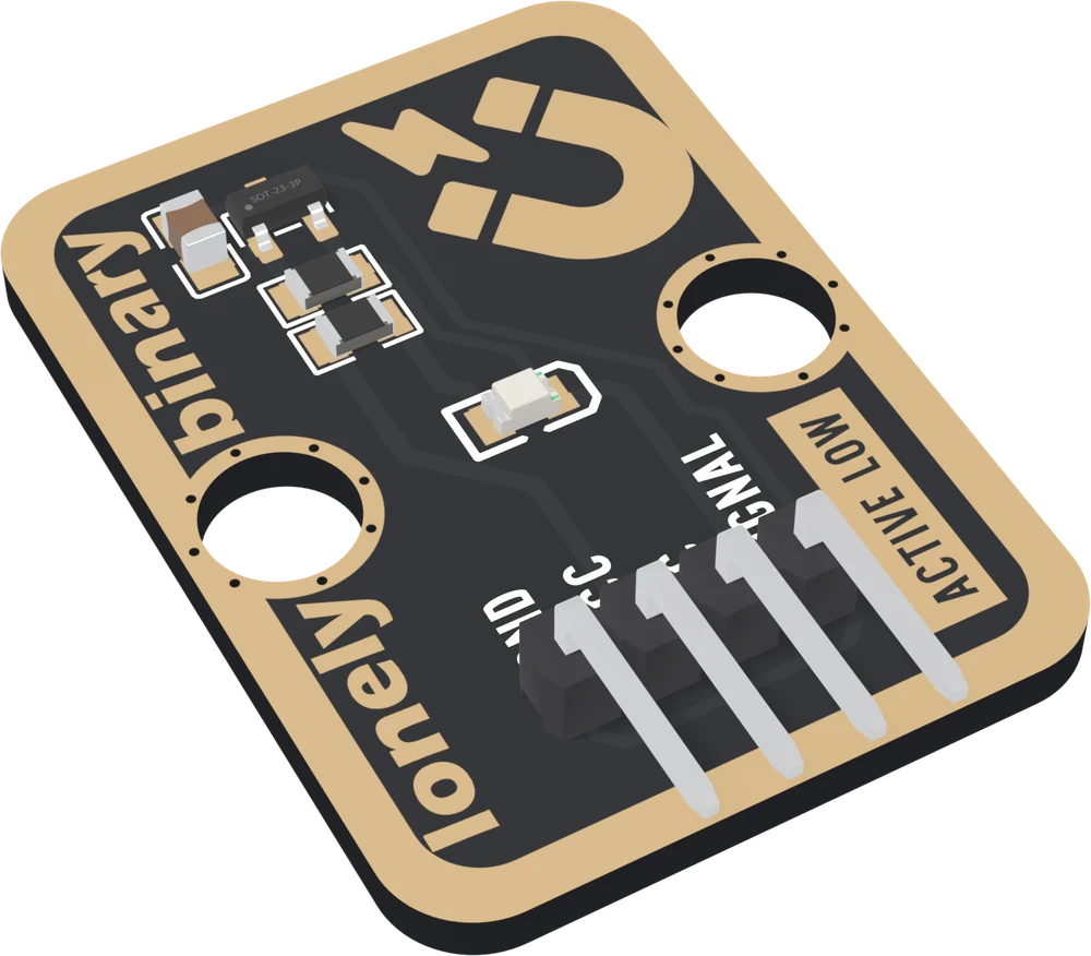
Nothing touches and nothing wears out, and a magnetic field passes straight through plastic, wood and glass. That is why door and lid sensors are built this way. The chip is a CrossChip CC6201, which responds to either pole, lets go when the magnet leaves, and saves power by looking at the field only once every 22 ms or so. That last part decides what it is for: a door or a lid that stays put for seconds, not a magnet flicking past on a fast wheel.
The page this replaces said it responds to one pole only, might latch, and reads HIGH for a magnet. All three were wrong.
VCC is the voltage your pin sees
With no magnet near, the chip drives SIGNAL up to VCC, so whatever is on VCC is what your pin sits at most of the time:
| Your board | VCC to | No magnet | Magnet | LED |
|---|---|---|---|---|
| Arduino Uno | 5V | 5 V, HIGH | near 0 V, LOW | about 3 mA, bright |
| ESP32, ESP32-S3, Pico | 3V3 | 3.3 V, HIGH | near 0 V, LOW | about 1.3 mA, a little dimmer |
Never 5V beside a 3.3 V board. The LED currents are worked out from its datasheet's forward voltage rather than measured.
Which pin is which
Parts up, header at the bottom, reading left to right:
| GND | to your board's GND | the square pad: count from here |
| VCC | to 3V3 or 5V | your board's logic voltage |
| NC | nothing | not connected on the board |
| SIGNAL | to a digital input | LOW while a magnet is near |
The back prints TK18 HALL EFFECT SENSOR instead of pin names. Turned over, the square pad is on the right, and it is still GND.
Wiring, in three lines
- GND to your board's GND.
- VCC to 5V on an Uno, 3V3 on an ESP32, ESP32-S3 or Pico.
- SIGNAL to a digital pin: D2 on an Uno, GPIO 25 on an ESP32, GPIO 4 on an ESP32-S3, GP15 on a Pico.
Leave NC unconnected. Set the pin to INPUT: the chip drives SIGNAL both
ways and the pull-up is already on the board.
Example
// The GPIO number SIGNAL is wired to.
// Uno: 2. ESP32: 25. ESP32-S3: 4. Pico: 15.
const int HALL_PIN = 4;

void setup() {
  Serial.begin(115200);
  pinMode(HALL_PIN, INPUT);   // the chip drives SIGNAL both ways
}

void loop() {
  if (digitalRead(HALL_PIN) == LOW) {   // active low: LOW is a magnet
    Serial.println("magnet");
  } else {
    Serial.println("no magnet");
  }
  delay(200);
}from machine import Pin
import time
# The GPIO number SIGNAL is wired to. ESP32: 25. ESP32-S3: 4. Pico: 15.
hall = Pin(4, Pin.IN) # the chip drives SIGNAL both ways
while True:
if hall.value() == 0: # active low: 0 is a magnet
print("magnet")
else:
print("no magnet")
time.sleep_ms(200)Where to start
The handbook below is ten short articles, each with a working figure. The first read is the whole build in three wires and a few lines.
If nothing happens when the magnet comes near, how far a magnet reaches is usually the answer. For a door or a lid, a door alarm is the project; for a wheel, read once every 22 ms first.
And before plugging it into an ESP32, VCC sets the level is the one page that protects the board.
When it doesn’t work
- Does it read HIGH or LOW when a magnet is near?
- LOW. The chip pulls SIGNAL to ground when it sees a magnet and lets it go back to VCC when the magnet leaves, and the red LED lights while it is LOW. The front of the board says ACTIVE LOW. Sketches that treat HIGH as the magnet, including the one this page used to show, get it backwards.
- Which pole do I need?
- Either. The CC6201 is omnipolar: a north pole and a south pole both switch it at about 40 gauss. What matters is where and how you hold the magnet: over the small chip at the top left, a flat face towards it. The gold magnet printed at the top right is only a picture.
- Does it latch?
- No. It is a switch: take the magnet away and SIGNAL goes back HIGH once the field falls below about 32 gauss. The gap between 40 and 32 is hysteresis, which stops a magnet at the edge of range from making the output flicker.
- How close does the magnet have to be?
- Closer than most people expect. Worked out from the magnet's field rather than measured, a 10 × 3 mm neodymium disc switches it from about 20 mm and a 5 × 2 mm disc from about 11 mm, face on and on axis. A flat fridge magnet may have to touch the board. No magnet is included.
- Should VCC go to 3V3 or 5V?
- To your board's logic voltage: 3V3 on an ESP32, ESP32-S3 or Pico, 5V on an Uno. With no magnet near, SIGNAL sits at VCC, so 5V on VCC puts 5 V on a 3.3 V pin for as long as the magnet is away.
- Can I use it to measure a motor's speed?
- Only a slow one. The chip looks at the field once every 22 ms or so, and a magnet that is in range for less than that can pass unseen. A wheel turning a few hundred times a minute is fine; a fan or a motor shaft is not.