Specifications
| Type | Ball tilt switch |
|---|---|
| Output | Digital, open or closed by orientation |
| Pull-up | Fitted on the module |
| Supply voltage | 3.3 V or 5 V |
What it is
A metal ball in a tube with two contacts at one end. Tilt it past roughly 30 degrees and the ball rolls off the contacts, opening the circuit.
It is a single axis and a single threshold — there is no angle and no direction, just above or below. For "has this been knocked over" or "is the lid open" that is the entire requirement, and it costs nothing.
For four directions in a plane, TK19 has one roller with four corner contacts. For an actual angle, you want an accelerometer, which is a different part and a lot more code.
Like every mechanical contact it bounces, and it also rattles when the board is moved rather than tilted. Require the same reading twice before believing it.
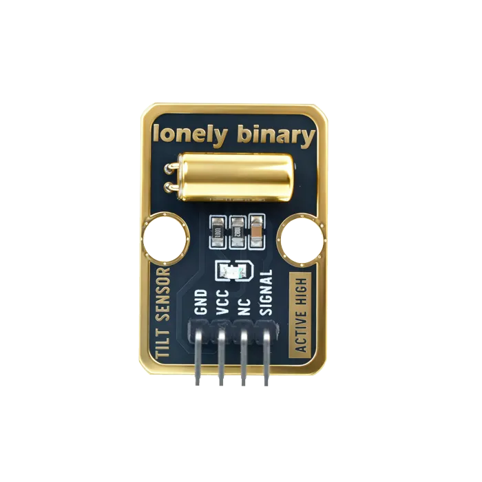
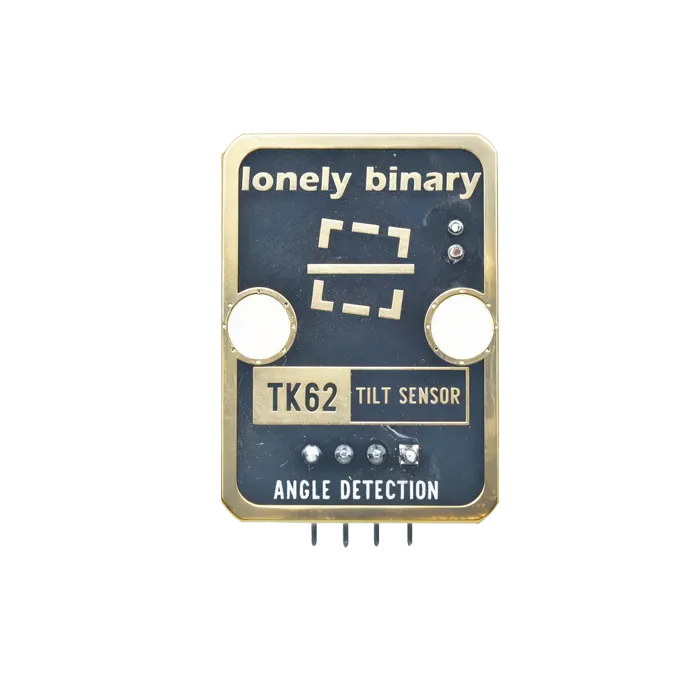
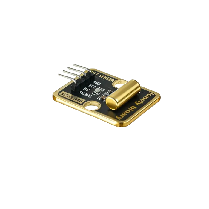
Pinout
- GND (negative): Like the negative terminal (-) of a battery, connect to the control board's GND
- VCC (positive): Like the positive terminal (+) of a battery, connect to the control board's 3.3V or 5V (this module supports both 3.3V and 5V)
- NC (no connection): No actual circuit connection, included for unified interface, can be left unconnected
- SIGNAL (signal output): Tilt detection output pin, connect to the control board's digital pin (e.g. Arduino D2 or Pico GPIO 0)
- Outputs HIGH (HIGH/1) when tilt detected
- Outputs LOW (LOW/0) when no tilt detected
Wiring
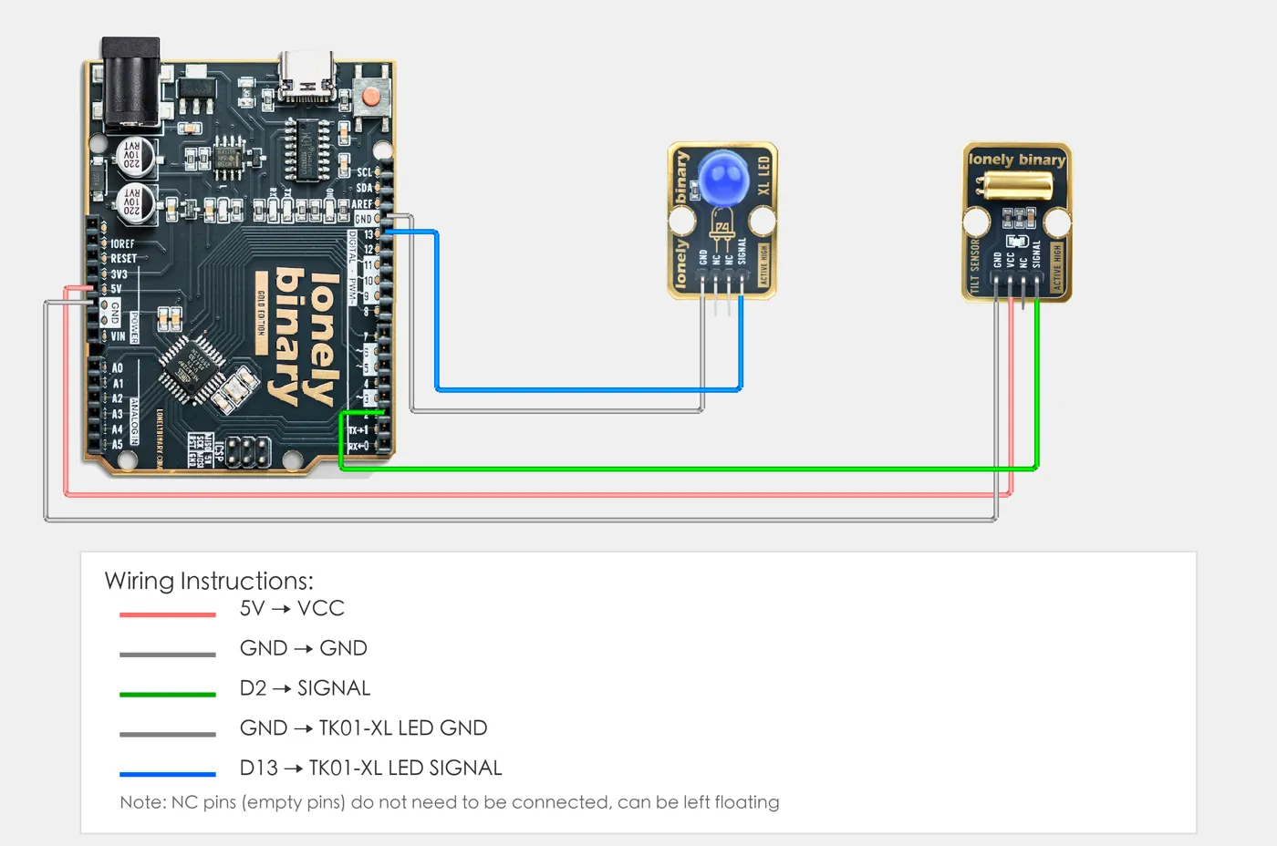
- GND → Control board GND
- VCC → Control board 3.3V or 5V
- SIGNAL → Control board digital pin (use the pin defined in your program)
Example
// Pin number: change this to match your wiring
#define TILT_PIN 2     // Arduino digital pin connected to SIGNAL (e.g. D2)
#define LED_PIN 13     // LED pin (Arduino built-in LED on pin 13, or external LED)

void setup() {
  // Initialize pin modes
  pinMode(TILT_PIN, INPUT);   // Set tilt sensor pin as input (to read detection state)
  pinMode(LED_PIN, OUTPUT);  // Set LED pin as output (to control LED on/off)

  // Start serial for debugging (9600 baud)
  Serial.begin(9600);

  Serial.println("Tilt sensor program started");
  Serial.println("LED on when tilt detected, LED off when level");
}

void loop() {
  // Read tilt sensor state
  int tiltState = digitalRead(TILT_PIN);  // Read sensor pin level: HIGH(1)=tilt, LOW(0)=level

  // Control LED based on detection state
  if (tiltState == HIGH) {
    // Tilt detected: LED on
    digitalWrite(LED_PIN, HIGH);
    Serial.println("Tilt detected - LED on");
  } else {
    // Level state: LED off
    digitalWrite(LED_PIN, LOW);
    Serial.println("Level state - LED off");
  }

  delay(100);  // Brief delay to avoid reading too fast
}# Import required modules
from machine import Pin # GPIO control
import time # For delay (time.sleep)
# Pin number: change these to match your wiring
TILT_PIN = 0 # GPIO connected to SIGNAL (e.g. GPIO 0)
LED_PIN = 1 # LED pin (GPIO 1, or external LED, Pico built-in LED is GPIO 25)
# Create pin objects
tilt = Pin(TILT_PIN, Pin.IN) # Set tilt sensor pin as input (to read detection state)
led = Pin(LED_PIN, Pin.OUT) # Set LED pin as output (to control LED on/off)
print("Tilt sensor program started")
print("LED on when tilt detected, LED off when level")
# Main loop: runs forever
while True:
# Read tilt sensor state
tiltState = tilt.value() # Read sensor pin level: 1=tilt (HIGH), 0=level (LOW)
# Control LED based on detection state
if tiltState == 1:
# Tilt detected: turn LED on and print message
led.on() # Output HIGH, LED on
print("Tilt detected - LED on")
else:
# Level state: turn LED off
led.off() # Output LOW, LED off
print("Level state - LED off")
# Delay 100 milliseconds to avoid reading too fast
time.sleep_ms(100)When it doesn’t work
- It flickers when I move the board.
- The ball is bouncing. Require the reading to be stable for 50 ms before acting on it.
- It does not trigger until quite far over.
- About 30 degrees is normal for a ball switch. If you need a smaller angle, use an accelerometer.
- Which state is upright?
- Depends which way you mounted it. Read it in both positions once and write down which is which.