Specifications
| Type | Spring vibration switch, normally open, active high |
|---|---|
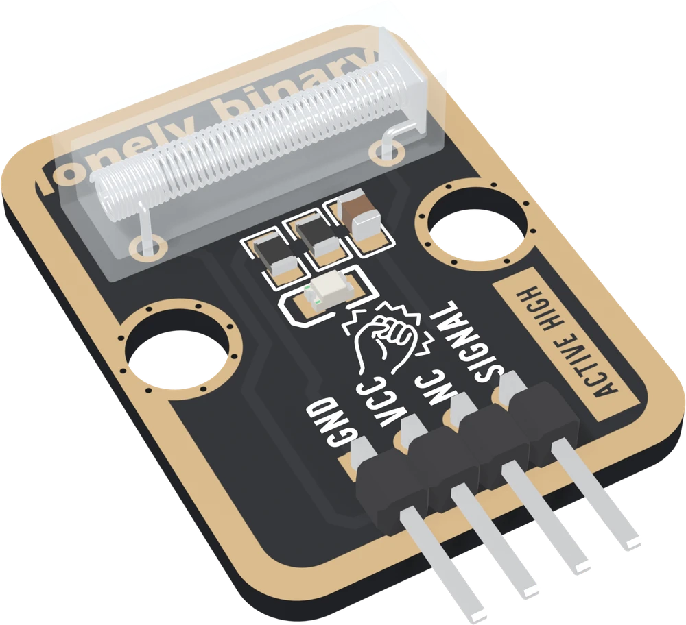
| Switch | SW-280 spring switch: a coiled spring around a centre rod in a clear body 18.2 × 5.7 × 5.6 mm, lying flat along the top of the board. A knock swings the spring onto the rod for a moment |
| Output | A burst of short HIGH pulses per knock, about a millisecond each, as the spring rings. Not an amplitude: a hard knock and a soft one read the same |
| Pull-down | 10 kΩ from SIGNAL to GND, on the board. At rest reads LOW, spring touching reads HIGH |
| Capacitor | 100 nF from SIGNAL to GND. Stretches each touch by a millisecond or less; one knock is still several pulses |
| Knock light | Red LED with a 1 kΩ resistor on SIGNAL. Flashes with each touch, about 3 mA from 5 V |
| Supply | 3.3 V or 5 V on VCC. During a touch, SIGNAL is at VCC, so use 3V3 beside an ESP32, ESP32-S3 or Pico and 5V beside an Uno |
| Current | Nothing at rest. About 3.5 mA from 5 V during a touch |
| Pins to wire | 3 of the 4: GND, VCC and SIGNAL. NC is connected to nothing on the board |
| Header | 4-pin right-angle male, 2.54 mm pitch: GND, VCC, NC, SIGNAL, with GND on the square pad |
| Board | 22.4 × 30.4 mm, two 4.8 mm mounting holes 16 mm apart; about 5.6 mm tall at the switch |
| In the box | 1 × TK28 block. It also ships inside the TinkerBlock kits |
What it is
A spring vibration switch, a 10 kΩ pull-down resistor, a 100 nF capacitor and a red LED. Inside the switch's clear body, a coiled spring hangs around a metal rod without touching it. Knock the board and the spring swings, touches the rod, bounces off and touches again; each touch joins SIGNAL to VCC for a moment, your board reads HIGH, and the LED flashes. Between knocks the pull-down holds SIGNAL at 0 V and your board reads LOW.
It is the TK17 collision sensor's circuit with a different switch and one extra part, and the switch is what shapes every sketch. A knock is not one pulse but a short burst of them, each about a millisecond long, so a sketch has to read the pin without waiting and count each burst once. It tells you that something shook the board; it cannot tell you how hard.
VCC is the voltage your pin sees
The switch joins SIGNAL straight to VCC, so whatever is on VCC is what your pin receives during every touch:
| Your board | VCC to | During a touch, SIGNAL is | Knock light |
|---|---|---|---|
| Arduino Uno | 5V | 5 V | about 3 mA |
| ESP32, ESP32-S3, Pico | 3V3 | 3.3 V | about 1.3 mA, dimmer |
Never 5V beside a 3.3 V board. With VCC unconnected, the block does nothing and the light never flashes. The LED currents are worked out from a red LED's typical forward voltage rather than measured.
Which pin is which
Switch at the top, header at the bottom, reading left to right:
| GND | to your board's GND | the square pad: count from here |
| VCC | to 3V3 or 5V | your board's logic voltage |
| NC | nothing | not connected on the board |
| SIGNAL | to a digital input | HIGH while the spring touches |
The back prints TK28 KNOCK SENSOR and SENSES VIBRATIONS instead of pin names. Turned over, the square pad is on the right, and it is still GND.
Wiring, in three lines
- GND to your board's GND.
- VCC to 5V on an Uno, 3V3 on an ESP32, ESP32-S3 or Pico.
- SIGNAL to a digital pin: D2 on an Uno, GPIO 25 on an ESP32, GPIO 4 on an ESP32-S3, GP15 on a Pico.
Leave NC unconnected. Set the pin to INPUT, not INPUT_PULLUP: the
pull-down is already on the board. On an Uno, D2 can also raise an
interrupt.
Example
Counts knocks, once each. It reads the pin on every pass of loop() and
never waits, because a pulse lasts about a millisecond.
// The GPIO number SIGNAL is wired to.
// Uno: 2. ESP32: 25. ESP32-S3: 4. Pico: 15.
const int KNOCK_PIN = 4;
const unsigned long HOLD_OFF_MS = 100;   // longer than the spring rings

int last = LOW;
unsigned long lastKnock = 0;
unsigned long knocks = 0;

void setup() {
  Serial.begin(115200);
  pinMode(KNOCK_PIN, INPUT);   // the block has its own pull-down
}

void loop() {
  int level = digitalRead(KNOCK_PIN);
  unsigned long now = millis();
  if (level == HIGH && last == LOW) {       // a pulse starts
    if (now - lastKnock >= HOLD_OFF_MS) {   // not the same knock
      knocks++;
      lastKnock = now;
      Serial.print("knocks: ");
      Serial.println(knocks);
    }
  }
  last = level;                // no delay(): it would miss knocks
}from machine import Pin
import time
# The GPIO number SIGNAL is wired to. ESP32: 25. ESP32-S3: 4. Pico: 15.
knock = Pin(4, Pin.IN) # no pull: the block has its own
HOLD_OFF_MS = 100
last = 0
last_knock = time.ticks_add(time.ticks_ms(), -HOLD_OFF_MS)
knocks = 0
while True:
level = knock.value()
now = time.ticks_ms()
if level == 1 and last == 0:
if time.ticks_diff(now, last_knock) >= HOLD_OFF_MS:
knocks += 1
last_knock = now
print("knocks:", knocks)
last = levelWhere to start
The handbook below is ten short articles, each with a working figure. The first read is the whole build in three wires, and prints every pulse so you can see the spring ring. Catching it with an interrupt is the version to build on, and a secret knock is a lock that opens to a rhythm.
And before plugging it into an ESP32, VCC sets the voltage is the one page that protects the board.
When it doesn’t work
- Does it read HIGH or LOW on a knock?
- HIGH. The board has a 10 kΩ pull-down, not a pull-up, and prints ACTIVE HIGH on its front: at rest SIGNAL sits at 0 V and reads LOW; each time the spring touches its rod, the switch connects SIGNAL to VCC and it reads HIGH. An interrupt goes on RISING, not FALLING.
- Why does one knock count as several?
- The spring rings. A knock throws it against the rod, it bounces off, swings across and touches again, and every touch is a separate pulse. Count the first change to HIGH and ignore the rest for about 100 ms. The handbook's sketches do it with millis() and no library.
- My sketch misses most knocks.
- Each pulse lasts about a millisecond, and a knock keeps SIGNAL HIGH for only a few milliseconds in all. A loop() with a delay(100) in it reads the pin ten times a second and sleeps through nearly every one. Read the pin in a loop that never waits, or attach an interrupt on RISING.
- Should VCC go to 3V3 or 5V?
- To your board's logic voltage: 3V3 on an ESP32, ESP32-S3 or Pico, 5V on an Uno. During a touch the switch connects SIGNAL straight to VCC, so the voltage on VCC is the voltage your pin receives. 5V on a 3.3 V board's pin is past its rating several times per knock.
- INPUT or INPUT_PULLUP?
- INPUT. The block brings its own pull-down. The chip's internal pull-up would fight it and leave the resting level somewhere around a volt, which no datasheet promises to read as LOW. In MicroPython, Pin(pin, Pin.IN) with no pull argument.
- Can it tell a hard knock from a soft one, or set its sensitivity?
- No to both. The switch is either touching or not, and there is no adjustment on the board. Whether a knock registers depends mostly on how firmly the block is fixed to what is being knocked. For how hard, use a sensor with an analog output, such as a piezo element.