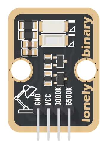
Specifications
| Type | Two white LEDs for light, not indication: a warm 3000K and a cool 6500K, each on its own pin, active high |
|---|---|
| LEDs | 5730 size, 5.7 × 3.0 mm, 120° beam. Rated 150 mA continuous and 500 mW each, 45 to 70 lm at 150 mA |
| Drive | Each LED through its own 10 Ω from VCC and its own S8050 transistor. About 168 mA from 5 V, 62 mA from 3.3 V. Worked out, not measured |
| Colour pins | 3000K and 6500K: each 1 kΩ into a transistor's base, and nothing else. About 2.6 mA from a 3.3 V pin. No pull-down: set the pins LOW first |
| Supply | 5V (VBUS on a Pico) for the most light, or 3V3 for about half. VCC only feeds the LEDs and never reaches a pin, so 5V is safe on a 3.3 V board |
| PWM | analogWrite 0 to 255 on each colour pin. On 5 V keep it at 170 or under: held fully on, the LEDs run a little past 150 mA |
| Current | Both at 170 on 5 V: about 224 mA averaged. Both fully on: about 336 mA from 5 V, 123 mA from 3.3 V. Off: nothing |
| Capacitors | 22 µF and 100 nF across VCC, for the edges of each PWM pulse |
| Pins to wire | All 4: GND, VCC, 3000K and 6500K. There is no NC pin |
| Header | 4-pin right-angle male, 2.54 mm pitch: GND, VCC, 3000K, 6500K, with GND on the square pad |
| Board | 22.4 × 30.4 mm, two 4.8 mm mounting holes 16 mm apart. The back prints the eye warning and USE PWM TO ADJUST BRIGHTNESS |
| In the box | 1 × TK95 block. It also ships in the TinkerBlock 46-piece kit |
What it does
It makes light, not a signal: two flat white LEDs of the kind used in LED strips and panel lights, one warm and one cool, each on a pin of its own. PWM on the pins sets how bright each one is, and sharing the duty between them gives any white from a filament bulb's to daylight's.
Your pins do not light them. Each colour pin goes through 1 kΩ into an S8050 transistor, and the transistor lets VCC push the LED's current through a 10 Ω resistor: about 168 mA from 5 V and 62 mA from 3.3 V. That is why VCC may be 5 V on a 3.3 V board, and why VCC has to be wired at all.
The page this replaces offered 3.3 V or 5 V as though they gave the same light, and blamed hot LEDs on a supply above what the resistors were sized for. The resistors are sized for 5 V, and from 5 V held fully on the LEDs run a little past their rating: that is why the back of the board says to use PWM, and why this book's sketches stop at two thirds. The workshop lesson wired the warm LED to D2, which cannot dim, and left VCC out of its list; both are corrected.
Two things to know before wiring
- VCC powers the light. Wire it to 5V (VBUS on a Pico) for the most light, and cap the PWM at 170 of 255; or to 3V3 for about half the light and no cap. Never to an Uno's 3.3V pin.
- Both colour pins need PWM. On an Uno that is D3, D5, D6, D9, D10 or D11; on an ESP32 or a Pico, any GPIO.
Wiring, in four lines
- GND to your board's GND.
- VCC to 5V, or VBUS on a Pico.
- 3000K to GPIO 4 on an ESP32-S3, GPIO 25 on an ESP32, D9 on an Uno, GP14 on a Pico.
- 6500K to GPIO 5 on an ESP32-S3, GPIO 26 on an ESP32, D10 on an Uno, GP15 on a Pico.
Then both pins LOW first, and analogWrite(pin, 0) to analogWrite(pin, 170) for each colour.
Where to start
The handbook below is nine short articles, each with a working figure. The first light is four wires and each white in turn. Warm, cool and between mixes them, and dimming with PWM fades them evenly.
For how it works, read the pin only switches it and five volts is the limit. If it will not light, when it stays dark.
When it doesn’t work
- Why does my board not power the LEDs from the colour pins?
- It is not meant to. Each colour pin feeds only a transistor's base through 1 kΩ, about 2.6 mA from a 3.3 V pin. The LEDs' current comes from VCC, so VCC must be wired, or nothing lights.
- Can I put VCC on 5V with an ESP32 or a Pico?
- Yes, and it gives the most light. VCC reaches only the LEDs' resistors and the capacitors, never a colour pin. On a Pico use VBUS, which is 5 V while it is on USB. On 5 V keep the PWM at 170 of 255 or under.
- Why cap the PWM at 170 on 5 V?
- Held fully on from 5 V, a typical LED here takes about 168 mA, a little past its 150 mA rating, and its 10 Ω resistor a little past a quarter watt. PWM lowers the average: at 170 of 255, two thirds, every LED in the maker's range averages under its limits. It is what the back of the board means by USE PWM TO ADJUST BRIGHTNESS.
- How do I get a white between the two?
- Light both and share the duty between them: 85 on each is about 4100 K. Keeping the two duties adding up to the same total keeps the brightness while the colour moves. The handbook's mix sketch walks from warm to cool in ten steps.
- Which pins can I use on an Uno?
- Two of the PWM pins: D3, D5, D6, D9, D10 or D11. The book uses D9 and D10. D2, which an older lesson used for the warm LED, has no PWM and only switches it fully on or off. VCC goes to 5V, never to the Uno's 3.3V pin.
- Is it safe to look at?
- Not up close. The back prints EYE HAZARD, EXTREMELY BRIGHT, DO NOT LOOK DIRECTLY. Point it at what you want lit and look at that.