One board, two sensors
Six boards, two sensors, one PCB design. Both carry the same 10 kΩ resistor and the same four pads labelled GND, VCC, NC and DATA — and the third of those is connected to nothing at all, which is the pin that catches people counting from the edge.
What is in the box
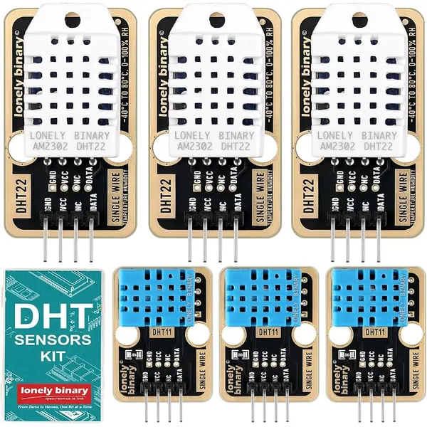
Six boards and a storage box. Nothing else is needed — no resistors, no capacitors, no breakout to solder — and the two kinds are told apart by the colour of the plastic cage rather than by anything you have to read.
The same board twice
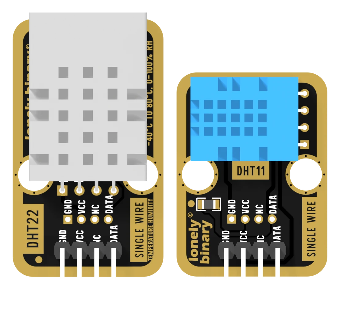
Set the two PCBs side by side and the difference is the part on top. The net lists are the same three nets on the same four pads, in the same order, with the same 10 kΩ resistor across two of them. So the wiring you learn on one is the wiring for all six boards.
Four things are worth pointing at.
GND is pin 1, and it has the square pad. That is not the order most DHT breakouts use, and it is not the order the bare sensor's own legs are in — the sensor is VCC, DATA, nothing, GND, and the board reverses it so that ground lands next to the ground on your header. Count from the square pad.
NC is real. The third pin is connected to nothing on either board. It is there because the sensor's third leg is unused, and it is the pin people count straight past when they are wiring by position rather than by label.
R1 is the pull-up you would otherwise have to add, 10 kΩ from VCC to DATA. Aosong's DHT11 datasheet suggests 5 kΩ for cable runs under 20 metres; 10 kΩ is what every DHT breakout on the market fits and it is fine on ordinary jumper wires. It is only worth knowing about if you ever run the sensor a long way from the board, where a smaller resistor pulls the line up faster.
The second set of four holes is a connector footprint, on the same three nets, with nothing fitted on either board. It is somewhere to solder a 2.0 mm cable, not a way to chain a second sensor.
The two sizes
| TK38 · DHT11 | TK39 · DHT22 | |
|---|---|---|
| Board | 22.4 × 33.9 mm | 22.4 × 42.9 mm |
| Cage | blue | white |
| Header | 4 pins, 2.54 mm | 4 pins, 2.54 mm |
| Pull-up | 10 kΩ, fitted | 10 kΩ, fitted |
Both have two large cut-outs for mounting and a gold-plated border. The back of
each prints its own TK number and its own range, which is how to identify a
loose board with no packaging: TK38 DHT11 over 0-50°C AND 20-80% RH, or
TK39 DHT22 over TEMPERATURE: -40°C TO 80°C.
When it does not work
The one on a square pad, at the end nearest the lonely binary logo. It is GND. Every other pad on the board is round, so you can find it by touch and in a photograph. The order left to right from there is GND, VCC, NC, DATA.
Nothing. It appears in no net on either board — the net list has three nets, and the third header pin is in none of them. It exists because the sensor inside has four legs and the third of those is unused too. Do not wire it to ground to tidy things up; wire nothing to it.
No. R1 on the board is a 10 kΩ from VCC to DATA and it is already fitted, on both boards. A bare DHT sensor with no breakout needs one added; these are not bare sensors. Adding a second in parallel does no harm but does nothing useful either.
The footprint for a 2.0 mm connector, carrying the same three nets as the header — GND, VCC, nothing, DATA. Nothing is fitted there on either board. It is a second way to attach a cable, not a pass-through to a second sensor.
Three wires, one library, and a sketch that prints a temperature.
The first reading →Edit this page — content/books/dht22/one-board-two-sensors.mdx
Questions about this product
See what other owners have asked, and read their solutions.
This page covers several products. Choose yours to see the right discussions.
Discuss this article
Ask about this page. The answer stays here, on the page it belongs to, for whoever hits the same wall next.