Five boards and four pins
Five identical boards, 46 × 26 mm, with everything you need to know printed on the back of each one — the mode table, the supply range, and a header whose first pin is square.
Both sides
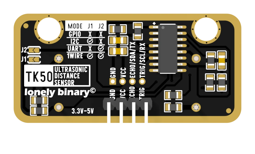
The front is the pair of aluminium cans, which is the half everybody recognises. The back is where the information is, and it is worth a minute because this board prints more about itself than most.
What is printed, and why it matters
3.3V-5V, in the bottom corner. That is the supply range, on the part
itself, and it is the single fact that separates this board from the HC-SR04
its listing is named after.
The mode table, in the top left — four rows, two columns, ticks and crosses. It is the truth table for the two solder pads beside it, and it means you never have to look anything up with the board in your hand.
J2 and J1, on the left edge, in that order top to bottom. Note the
order: J2 is the upper one. It is an easy thing to get backwards with an iron
in your hand and a magnifier in the other.
ECHO/SDA/TX and TRIG/SCL/RX, beside the last two pins. One pin, three
names, because one board serves four protocols —
one pin, three names
untangles which name applies when.
The pins
| Pin | GPIO | I2C | UART | 1-Wire | |
|---|---|---|---|---|---|
| 1 | GND — square pad | GND | GND | GND | GND |
| 2 | VCC | 3.3–5 V | 3.3–5 V | 3.3–5 V | 3.3–5 V |
| 3 | ECHO | Echo | SDA | TX | not used |
| 4 | TRIG | Trigger | SCL | RX | Data |
Left to right on the back, pins pointing down. From the front the order reverses, which is the usual way to end up with VCC and GND swapped.
What is underneath
One chip does everything: an RCWL-9610A in a 16-pin package, in the middle of the board. Around it are the two transducers — a HY40A16T12-1 transmitter and a HY40A16R12-1 receiver, 16 mm across, 40 kHz — and a handful of resistors setting the gain of the receiving amplifier.
Two of those resistors are the interesting ones. Each runs from a chip pin to one of the jumper pads, whose other side is ground, and they are 10 kΩ. That is the mode-select circuit, and it is two solder bridges away from being interesting.
Five of them
Enough to put one on each side of a robot and still have a spare, which is the argument for a pack rather than a part. It is also enough to commit one or two to a soldered mode and leave the rest as they came — a bridge is not something you undo casually.
When it does not work
Count from the square pad, which is GND. The order from there is GND, VCC, ECHO, TRIG. Once the board is in a breadboard the printed names are face down and the square pad is the only marking you can still see, which is why every sketch in this handbook says to count from it.
A 2.0 mm connector footprint on the same four nets, left unfitted. It is where the TinkerBlock cable plugs in when you buy that connector separately. It is not a second pinout — soldering to it gets you exactly the header's pins in the same order.
The 3D model and the renders show the four-pin header soldered in place, which is how the TinkerBlock boards are normally supplied. Check your own box before planning a build around it, because a bag of loose headers means an evening with a soldering iron first.
Only if the two cans can see out. They need clear air in front of them — a hole each, not a grille and not a sheet of plastic across the front. A cover over the transmitter muffles the burst; a cover over the receiver muffles the echo; either one shortens the range dramatically.
Edit this page — content/books/ultrasonic-sensor/five-boards-and-four-pins.mdx
Questions about this product
See what other owners have asked, and read their solutions.
Ultrasonic Distance Sensor
Loading discussions…
Discuss this article
Ask about this page. The answer stays here, on the page it belongs to, for whoever hits the same wall next.