What is on it
A coin motor rated 3.0 V, and five parts that do one job each: a MOSFET that switches it, a 10 kΩ that keeps it off, a 3.3 V regulator that feeds it, a diode that protects the switch, and an LED that shows it is being driven. Two 10 µF capacitors and a 100 nF steady the supply.
One motor, five helpers
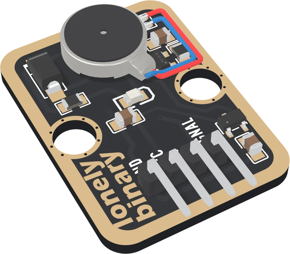
A small motor draws tens of milliamps, and more for a moment as it starts. That is more than a microcontroller's pin should give, and a motor also does things to a supply that a pin does not like. So a vibration board is mostly a driver, and this one has five parts in it.
Pick each part in turn. The ring shows where it sits, and the sentence under the drawing is its job.
The motor
A LEADER LCM1027A2445F: a coin vibration motor 10 mm across and 2.7 mm thick. Its datasheet rates it at 3.0 V, for use between 2.7 and 3.3 V, turning at 13,500 rpm give or take 3,500, and drawing at most 80 mA running and 120 mA as it starts. It is not a 5 V part, and that is the reason for the regulator.
The switch and the resistor that keeps it off
The MOSFET is the switch. Its gate is SIGNAL, and when the gate is HIGH it joins the motor's − lead to GND. The 10 kΩ from the gate to GND is what keeps the motor off when nothing drives SIGNAL: at power-up, during a reset, or with the wire out. A switch in the ground wire is about both.
The regulator
A 3.3 V regulator, the XC6206P332MR, takes VCC in and gives 3.3 V out, and the motor's + lead is on that output. So the motor gets 3.3 V, the top of its range, whether VCC is 5 V or 3.3 V (a little less from 3.3 V). The next chapter follows what that means for wiring.
The diode, the light and the capacitors
An SS14 diode sits across the motor, pointing back at the supply. It catches the current the motor keeps pushing when it is switched off, which would otherwise land on the MOSFET as a spike. The LED and its 1 kΩ run from the 3.3 V to the MOSFET, so the LED lights while the switch is closed. The diode and the light has both.
The two 10 µF capacitors are the regulator's own, one on its input and one on its output; they supply the motor's starting surge faster than the regulator can. The 100 nF across the motor soaks up the fast electrical noise a small motor makes as it turns.
When it does not work
There is one, and you need nothing else. It is a MOSFET, the AO3400A, the small three-legged part to the right of the motor, just above its leads. It carries the motor's current, so your board's pin only has to drive its gate.
They are meant to be free. The motor comes with two fine leads, red for + and blue for −, and they run from the tab on the motor round to two pads on the right. They are thin, so do not hook the board by them or bend them at the solder.
Because this motor is made for 2.7 to 3.3 V. Wired straight to 5 V it would run well outside its datasheet's range. The regulator holds it at 3.3 V whatever VCC is, as long as VCC is a few tenths of a volt above that; from 3V3 it gets a little less.
What SIGNAL actually does, and why a 3.3 V pin is more than enough for it.
A switch in the ground wire →Edit this page — content/books/vibration-motor/what-is-on-it.mdx
Questions about this product
See what other owners have asked, and read their solutions.
Vibration Motor
Loading discussions…
Discuss this article
Ask about this page. The answer stays here, on the page it belongs to, for whoever hits the same wall next.