The six pins
Six pins, five of them wired. GND and VCC power the block, CLOCK and DATA are the two contacts that report a turn, BTN is the switch in the shaft, and NC is connected to nothing. CLOCK and DATA rest HIGH; BTN reads HIGH only while the knob is pushed in.
What is on the board
An EC11-type rotary encoder lying on its side, with a blue knob on its shaft, five small parts along the top edge and the right-hand side, and a six-pin header along the bottom edge. The shaft points out past the top of the board, so the knob stands clear of it. The header is right-angled, so the pins point out past the bottom edge and the board lies flat.
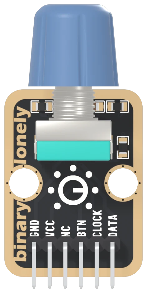
The encoder is an EC11-type part, a size and pin layout many makers build, in its horizontal form with a push switch in the shaft. The shaft is 6 mm across, on a threaded M7 bushing. The five small parts are three 10 kΩ resistors and two 100 nF capacitors: a pull-up and a capacitor for each of the two rotation contacts, and a pull-down for the switch.
The six names
GND is on the square pad. It is also the encoder's common contact: when either rotation contact closes, it joins its line to GND.
VCC goes to the two pull-ups and one side of the shaft switch, and nowhere else. So the voltage on VCC is the voltage all three signals reach. That is the next article.
NC means not connected, and here it means it literally. The net list, the list of every electrical connection on the board, does not mention it.
BTN is the switch in the shaft. Released, it reads LOW. Push the knob in and it reads HIGH.
CLOCK and DATA are the two contacts that report a turn. At rest both read HIGH, held up by their pull-ups. Turning the knob closes and opens them in turn, and each one reads LOW while it is closed.
Five wires, not three
The push button in the kit needs three wires. This block needs five: power, ground, and three signals. The rotation is two signals, not one, because one contact on its own can say that the knob moved but not which way. Two contacts out of step is how the second one supplies the direction.
The back of the board
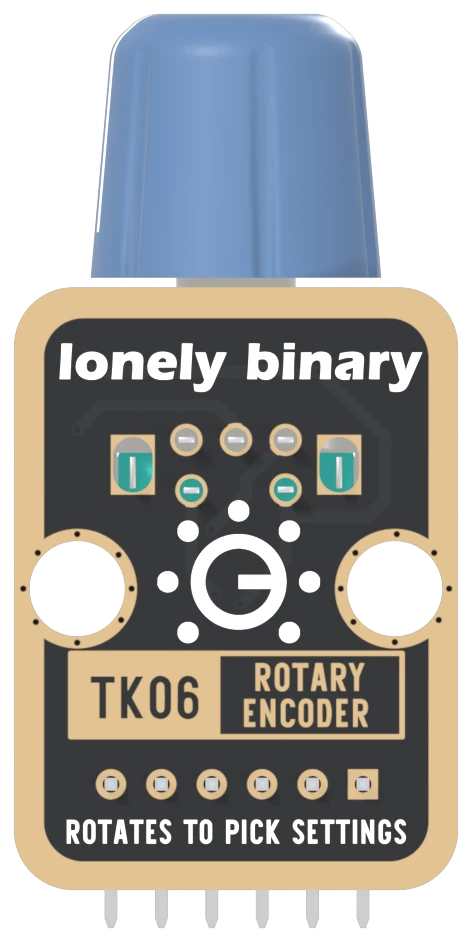
Turned over, the order reverses. The square pad is on the right, and it is still GND. The back prints TK06, the number on the box, and ROTATES TO PICK SETTINGS, which is what an encoder is for: a knob with no end stop that moves a value up and down rather than setting it to a position.
When it does not work
Hold the board with the knob pointing away from you and the header pins pointing towards you. Read GND, VCC, NC, BTN, CLOCK, DATA from left to right. GND is also the square pad, which is the one mark that survives when the labels are hidden in a breadboard.
No. It is not connected to anything on the board, on either side. A cable that carries a wire to it does no harm, and the wire simply ends at a pin that goes nowhere.
Turned over, the order reverses: DATA is on the left and GND on the right, and GND is still the square pad. The back prints TK06 ROTARY ENCODER and ROTATES TO PICK SETTINGS instead of the names. Count from the square pad and you cannot get it backwards.
Those were written for boards whose switch is pulled up. This block has a 10 kΩ pull-down on BTN and the switch goes to VCC, so released reads LOW and pushed reads HIGH. Test for HIGH.
Why the block's VCC pin goes to 3V3 beside an ESP32 and 5V beside an Uno.
VCC sets all three levels →Edit this page — content/books/rotary-encoder/the-six-pins.mdx
Questions about this product
See what other owners have asked, and read their solutions.
Rotary Encoder
Loading discussions…
Discuss this article
Ask about this page. The answer stays here, on the page it belongs to, for whoever hits the same wall next.