The receiver, pin by pin
Four pins, one three-legged chip and a resistor you cannot see. SIGNAL idles HIGH and goes LOW while a remote is sending, which is the opposite of what most people expect of a sensor, and the red LED shows it before any code runs.
What is on the board
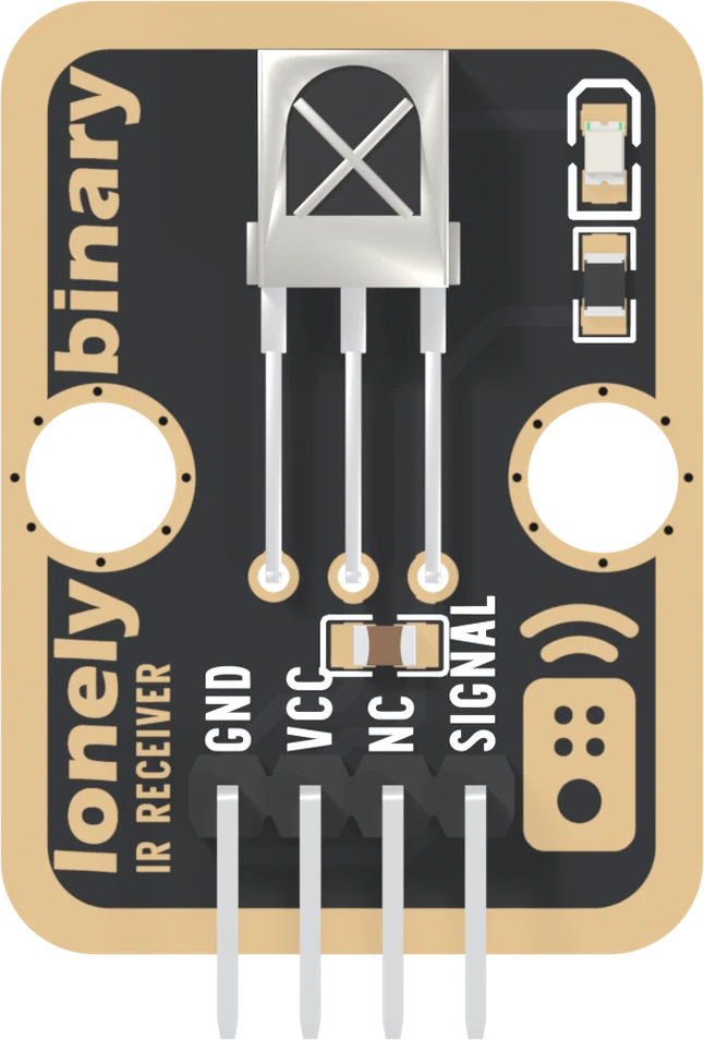
One chip does the work: a Vishay TSOP18138, bent over so it lies flat inside a steel shield, looking out through the X-shaped window. Its legs are OUT, GND and VS, left to right. Everything else is support: a 100 nF capacitor across the supply, and a red LED with a 1 kΩ resistor.
A shield like this is there to keep electrical noise off the amplifier inside; the window lets infrared in. The receiver looks out of the parts side of the board, so that side faces the remote.
The four pins
GND is on the square pad; count from it. VCC feeds the chip, the capacitor and the red LED. NC is connected to nothing.
SIGNAL is the chip's own output, and three things about it matter. It is active low: a burst of 38 kHz pulls it to near 0 V, and no burst lets it rise. It is weakly high: the only thing holding it up is a 30 kΩ resistor inside the chip. And it can sink 5 mA but source almost nothing, so read it and never power anything from it.
A burst becoming a low
There is no clock and no data line: one wire whose level goes down while light of the right kind is arriving. Everything a remote says is in how long the line stays down and how long it stays up.
The red LED
It runs from VCC, through its resistor, down into SIGNAL, so it lights whenever the chip pulls SIGNAL low: it flickers while a remote is sending, whether or not any code is running. That one observation separates "the remote, the board or the wiring" from "the sketch", and it costs nothing.
It gets about 3 mA on 5 V and about 1.2 mA on 3.3 V, where it is a little dimmer.
Which VCC
The chip runs from 2.0 to 5.5 V, and SIGNAL idles at whatever VCC is. So VCC is your board's own logic voltage: 5V on an Uno, 3V3 on an ESP32, ESP32-S3 or Pico. Fed 5 V beside a 3.3 V board, SIGNAL would idle at 5 V on a pin rated for 3.3.
When it does not work
That is the idle state. SIGNAL is HIGH until a burst arrives, and each low in a NEC frame lasts 560 microseconds. A loop that reads the pin every few milliseconds misses almost all of them, which is why the library samples it on a timer every 50 microseconds instead.
No. There is a 30 kΩ pull-up inside the chip. An external pull-up changes nothing; a strong pull-down breaks it, because the chip's 30 kΩ cannot lift the line against one and it never reads HIGH again.
No: it is held HIGH through 30 kΩ and can supply almost nothing. It can sink up to 5 mA, which is how the board's own red LED is wired, from VCC down into SIGNAL. Read the pin; let your sketch drive anything else.
Vishay suggests a series resistor and a 4.7 µF capacitor on the supply where there is ripple. This board fits only a 100 nF capacitor, so a motor or an LED strip on the same rail can reach the amplifier inside. Give it a quiet 3.3 V or 5 V.
No. It is a Vishay TSOP18138, a different maker's part with a documented datasheet: a supply range of 2.0 to 5.5 V, a 30 kΩ internal pull-up and a ±45° half angle. Most of what is written about the VS1838B does not apply to it.
Three wires and a library, and every button on the remote prints its own number.
Your first key code →Edit this page — content/books/ir-receiver/the-receiver-pin-by-pin.mdx
Questions about this product
See what other owners have asked, and read their solutions.
This page covers several products. Choose yours to see the right discussions.
Discuss this article
Ask about this page. The answer stays here, on the page it belongs to, for whoever hits the same wall next.