The four pins
Four pins, three of them wired. GND and VCC go to the two ends of a 10 kΩ potentiometer, SIGNAL is the contact that slides between them, and NC is connected to nothing. A small red LED also hangs off SIGNAL, and it matters more than it looks.
What is on the board
A potentiometer standing on the top edge, with its shaft and a pale-green knob pointing out past it, a small resistor, a small LED, and a four-pin header along the bottom edge. The header is right-angled, so the pins point out past the edge of the board and it lies flat in a breadboard or on a cable.
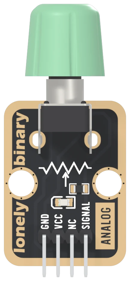
The potentiometer is a 10 kΩ linear part: 10 kΩ of track from end to end, with a contact that slides along it as you turn. Linear means equal turns cover equal lengths of track. The two metal tabs either side of its body are there to hold it down; the electrical pins are the three between them.
The four names
GND is on the square pad. One end of the track is soldered here, and the red LED returns here too.
VCC goes to the other end of the track and nowhere else. The knob's range is 0 V to whatever you connect here.
NC means not connected, and on this board it means it literally. The net list, the list of every electrical connection on the board, does not mention it at all.
SIGNAL is the wiper, the sliding contact. Its voltage is anywhere between GND and VCC, so it goes to an analog pin: one that measures a voltage, rather than a digital pin that only says HIGH or LOW. The schematic writes "Arduino A0" beside it.
The part that is not a potentiometer
The 1 kΩ resistor and the red LED between the potentiometer and the header are wired from SIGNAL to GND. Turn the knob up and the LED starts to glow about two-fifths of the way round on a 5 V board, and about three-fifths on a 3.3 V one. That is a handy check that the block is powered. It also means the LED takes its current from the voltage you are measuring, and the third chapter, the light on the wiper, is about what that does to the reading.
The back of the board
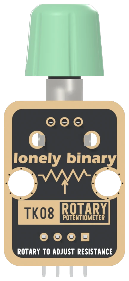
Turned over, the order reverses. The square pad is on the right, and it is still GND. The back prints TK08, the number on the box.
When it does not work
Hold the board with the knob pointing up and the header pins pointing down. Read GND, VCC, NC, SIGNAL from left to right. GND is also the square pad, which is the one mark that survives when the board is in a breadboard and the labels are hidden.
No. It is not connected to anything on the board, on either side. It is there so every TinkerBlock block has the same four-pin header and one cable fits all of them. Wiring it does no harm and changes nothing.
Turned over, the order reverses: SIGNAL is on the left and GND on the right, and GND is still the square pad. The back prints TK08 ROTARY POTENTIOMETER and ROTARY TO ADJUST RESISTANCE instead of the names. Count from the square pad.
None of the part's documents give an angle. Potentiometers of this style typically turn about 300 degrees between two end stops. Do not force it past a stop: the stop is a small tab inside the body, and the reading at the end is already the full range.
Why the wiper's voltage is a share of VCC, and which share.
A divider you can turn →Edit this page — content/books/rotary-potentiometer/the-four-pins.mdx
Questions about this product
See what other owners have asked, and read their solutions.
Rotary Potentiometer
Loading discussions…
Discuss this article
Ask about this page. The answer stays here, on the page it belongs to, for whoever hits the same wall next.